Friction facing clearance adjustment, Maintenance – Nexen BD 933702 User Manual
Page 6
6
FORM NO. L-21098-C-0609
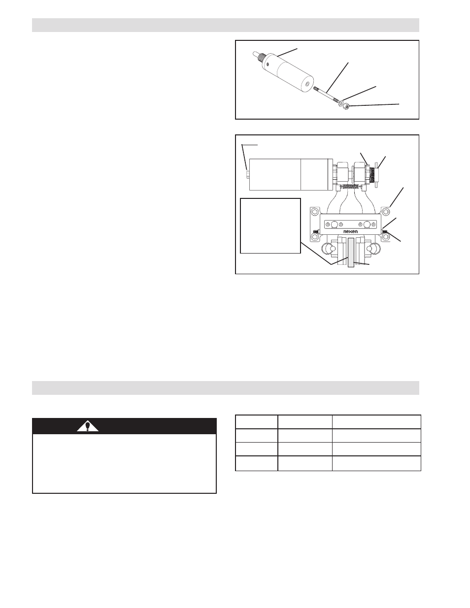
Vent
(item 17)
frICTION fACINg CLEArANCE ADJUSTMENT
1. Remove the Vent (Item 17) from the back of the Actuator.
2. Using the Nexen Manual Release Kit (Product No. 933710),
manually release the brake by inserting the Class 8.8 M10 x
1.5 x 5.5'' Threaded Rod into the back of the Actuator; then,
using the Flat Washer and Nut, tighten the Nut to release
the brake (See Figure 5).
3. Loosen the adjustment screw Spanner Nut (Item 12) (See
Figure 6).
4. Loosen the Set Screws (Item 50) and the Hex. Nuts (Item 51)
on the Main Frame (Item 1) (See Figure 6).
5. Turn the Adjustment Screw (Item 8) out until 1/32'' [0.8 mm]
spacers can be slid between each of the Friction Facings
(Item 4) and the Friction Disc (See Figure 6).
6. Turn the Adjustment Screw (Item 8) in until the spacers can
be just pulled out.
7. Tighten the Spanner Nut (Item 12) to 10-15 ft-lb [13.6-20.3
Nm] torque.
8. Adjust the Set Screws (Item 50) until they touch the Brake
Arms (Item 2) and tighten the Hex. Nuts (Item 51) on the
Main Frame (Item 1).
9. Loosen the Nut to manually reset the brake.
10. Remove the Threaded Rod, Nut, and Washer.
11. Screw the Vent (Item 17) into the back of the Actuator until
hand tight and continue to tighten one and one-half turns.
NOTE: The vent in the Rear Cylinder prevents debris from
entering the nested spring stack and relieves any pressure
built up by the reciprocating action of the Piston.
Flat Washer
Nut
Actuator
FiGuRE 5
Threaded Rod
Adjustment
Screw (item 8)
Spanner Nut
(item 12)
Friction Disc
FiGuRE 6
51
50
MAiNTENANCE
TABLE 3
1
1/32" [0.8 mm]
spacer between
each of the
Friction Facings
(item 4) and
Friction Disc.
M
E
T
I
N
O
I
T
P
I
R
C
S
E
D
E
U
Q
R
O
T
4
2
w
e
r
c
S
p
a
C
]
m
N
1
.
5
-
5
.
4
[
b
l-
n
i
5
4
-
0
4
2
1
t
u
N
r
e
n
n
a
p
S
]
m
N
3
.
0
2
-
6
.
3
1
[
b
l-
tf
5
1
-
0
1
8
1
w
e
r
c
S
e
n
i
h
c
a
M
]
m
N
5
1
-
2
1
[
b
l-
tf
2
1
-
8
1. Adhere to the following bolt torques (See Table 3).
DANGER
Never use your hand to check the condition of the hy-
draulic lines. If hydraulic fluid penetrates the skin, get
medical help immediately. Failure to get proper medical
help may result in loss of limb or life. The safest way
to check hydraulic lines for leaks is by holding a piece
of cardboard next to the hydraulic line.
2. Check tightness and condition of hydraulic lines. Replace
hydraulic lines if signs of deterioration exist.
3. Inspect friction facings for wear. Replace if worn to
approximately 5/32" [4 mm] thick.
4. Lubricate items requiring lubrication (See
LuBRiCATiON).