Actuator – Nexen BD 933702 User Manual
Page 9
9
FORM NO. L-21098-C-0609
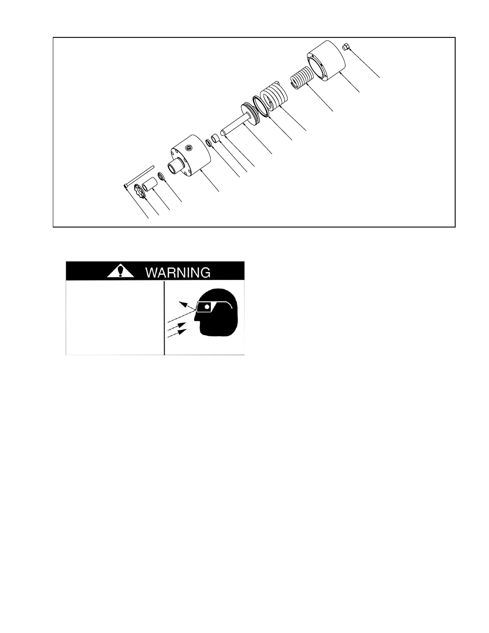
FiGuRE 11
ACTUATOR
1. Disengage the hydraulic supply from the Actuator and plug
the hydraulic ports in the Actuator.
NOTE: This BD Caliper Brake is spring engaged and
hydraulically disengaged. To release the spring pressure,
remove the Vent, then lubricate and insert a Class 8.8 M10
x 1.5 x 5.5" Threaded Rod into the back of the Actuator;
then, using a Flat Washer and Nut, tighten the Nut to release
the spring pressure (See Figure 12). A Manual Release Kit
(Product No. 933710) containing these items is available
from Nexen.
2200 lb [9786 N] of force is required to compress the
springs.
2. Loosen the Spanner Nut (Item 18) locking the Actuator to
the BD Caliper Brake and remove the Actuator.
3. Slowly release the pressure on the actuator by unscrewing
the Nut in the Threaded Rod.
4. Remove the six Socket Head Cap Screws (Item 10).
5. Separate the Rear Cylinder (Item 3) from the Front Cylinder
(Item 2).
6. Push the Piston (Item 1) out of the Front Cylinder (Item 2).
NOTE: Be careful not to scratch the Piston (Item 1) when
removing or installing the Retaining Ring (Item 11).
NOTE: The Piston Seal is coated with a special compound.
Avoid excessive handling of the Piston Seal.
7. Remove the Piston Seal (Item 5) from Piston (Item 1) and
install a new seal.
8. Remove both Sleeve Bearings (Items 7 & 11). Special tool
may be required for removal.
NOTE: The Rod Seal (Item 6) is coated with a special
compound. Avoid excessive handling of the Rod Seal.
While removing the Rod and Wiper Seals, note the orientation
of the seals to assure proper installation of the new seals.
9. Remove and replace both the Wiper Seal (Item 4) and the
Rod Seal (Item 6) with new seals.
10. Press new Sleeve Bearing (Item 11) into the Front Cylinder
(Item 2). This bearing must be pressed in 0.100 in. (2.54
mm) from the face of the Front cylinder (Item 2). (See Figure
11).
11. Press a new Sleeve Bearing (Item 7) into the Front Cylinder
(Item 2). This bearing must be flush with the end of the Front
Cylinder (Item 2). (See Figure 11).
12. Push the Piston (Item 1 into the Front Cylinder (Item 2).
Be careful not to damage the Piston Seal (Item 5) during
assembly. A light film of oil around the seal may help during
installation.
13. Put both the Inner Spring (Item 12) and the Outer Springs
(Item 13) into the Rear Cylinder (Item 3).
14. Align the bolt holes of the Front and Rear Cylinders (Items
2 & 3) together. Assure that the Inner and Outer Springs
(Items 12 & 13) are not making contact with each other.
15. Apply a drop of Loctite
®
242 to the six Socket Head Cap
Screws and thread them into the Rear Cylinder (Item 3).
Tighten the Cap Screws to 301-392 in-lb [34-44.3 Nm].
The Actuator is spring
loaded.
Always wear safety
goggles when working
with spring loaded
devices.
10
18
7
4
2
6
11
9
1
5
13
12
3
17