Replacement parts, Parts list – Nexen BD 933617 User Manual
Page 10
10
FORM NO. L-20271-F-0609
15. Remove the Belleville Disc Springs (Item 8) and Thrust
Washer (Item 16) from the Rear Cylinder (Item 3) (See
Figure 11).
16. Coat the Thrust Washer (Item 16) with grease and slide
it into the Rear Cylinder (Item 3) (See Figure 11).
17. Liberally coat the 36 Belleville Disc Springs (Item 8) with
grease and stack them in series into the Rear Cylinder
(Item 3) (See Figure 11 and Insert A).
NOTE
Start first Belleville Disc Spring with its concave side
facing towards the Thrust Washer (Item 16).
18. Place the Small Washer (Item 15) on the Front Cylinder
(Item 2); then, place the Cylinder Head (Item 12) onto the
Front Cylinder and Small Washer (See Figure 11).
19. Press the Piston (Item 1) into the Front Cylinder and
Cylinder Head (See Figure 11).
20. Thread the two Alignment Pins (provided with the Actuator
Repair Kit, Product No. 933597) into the Rear Cylinder
(Item 3).
21. Align the hole patterns of the Cylinder Head and Front
Cylinder with the hole pattern of the Rear Cylinder; then,
slide the Cylinder Head and Front Cylinder over the
Alignment Pins.
REPLACEMENT PARTS
The item or balloon number for all Nexen products is used
for part identification on all product parts lists, product price
lists, unit assembly drawings, bills of materials, and instruction
manuals.
When ordering replacement parts, specify model designation,
item number, part description, and quantity. Purchase
replacement parts through your local Nexen Distributor.
PARTS LIST
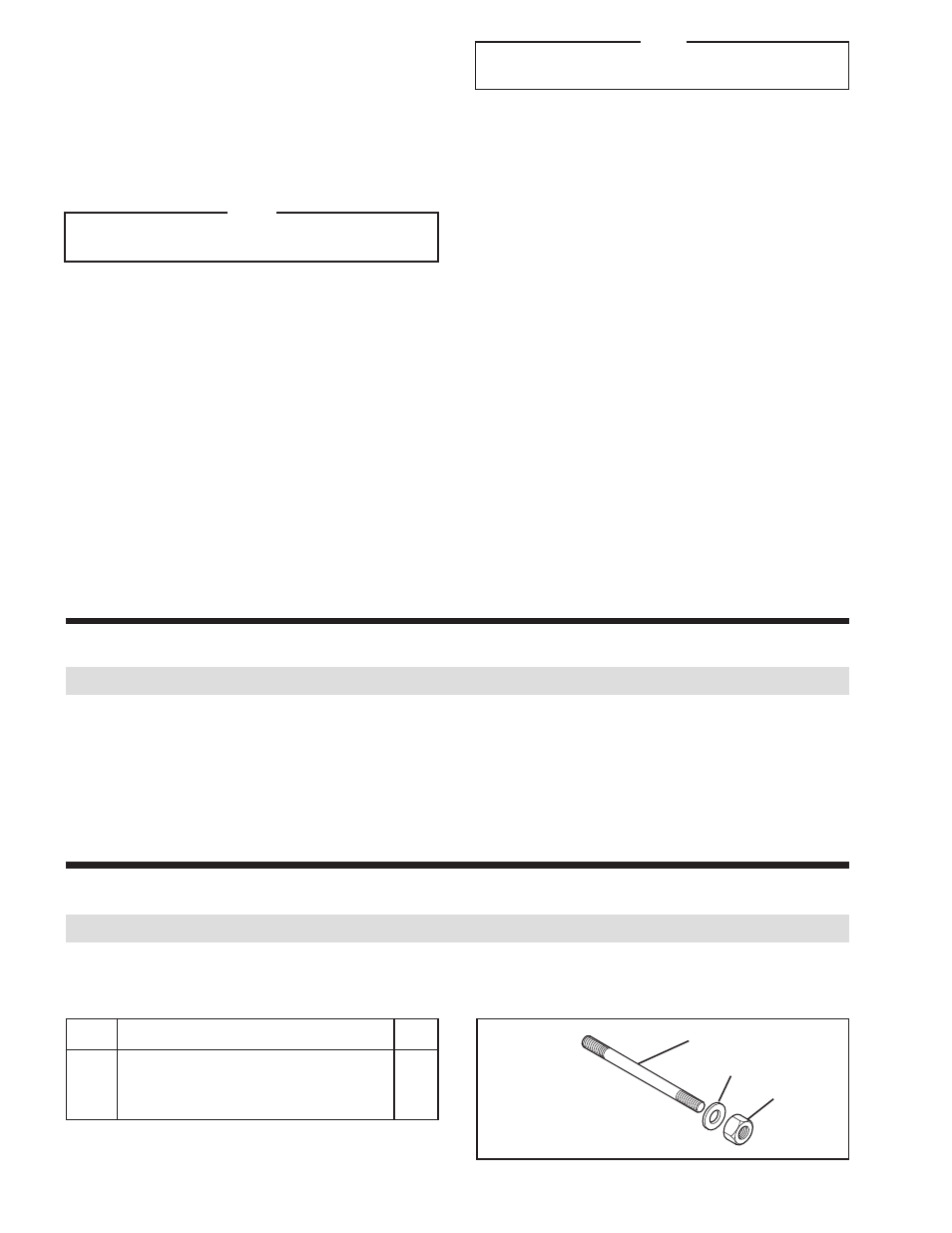
MANUAL RELEASE KIT (Product No. 933596)
ITEM
DESCRIPTION
QTY
1
Grade 5, 3/8-16 x 9'' Threaded Rod
1
2
3/8-16 Nut
1
3
3/8 Flat Washer
1
FIGURE 12
1
2
3
NOTE
1,500 Lbs. [6,672 N] of force is required to compress
the Belleville Washers.
22. Reinstall the Threaded Rod, Flat Washer, and Nut into
the back of the Actuator.
23. Tighten the Nut until the Belleville Disc Springs (Item 8)
are compressed and the Front Cylinder (Item 2) is flush
with the Rear Cylinder (Item 3).
24. Apply a drop of Loctite
®
242 to the threads of four Socket
Head Cap Screws (Item 10) and thread them into the
Rear Cylinder (See Figure 11).
25. Remove the two Alignment Pins.
26. Apply a drop of Loctite
®
242 to the threads of the two
remaining Socket Head Cap Screws (Item 10) and thread
them into the Rear Cylinder (See Figure 11).
27. Alternately and evenly tighten the six Socket Head Cap
Screws (Item 10) to 12 Ft. Lbs. [16.2 N•m] torque.
28. Reinstall the Actuator onto the BD Brake.
29. Loosely attach the Spanner Nut (Item 12) on the
Actuator.
30. With the manual release still installed, perform friction
facing adjustment. (See
FRICTION FACING CLEARANCE
ADJUSTMENT).