Lubrication, Parts replacement – Nexen BD 933617 User Manual
Page 7
7
FORM NO. L-20271-F-0609
LUBRICATION
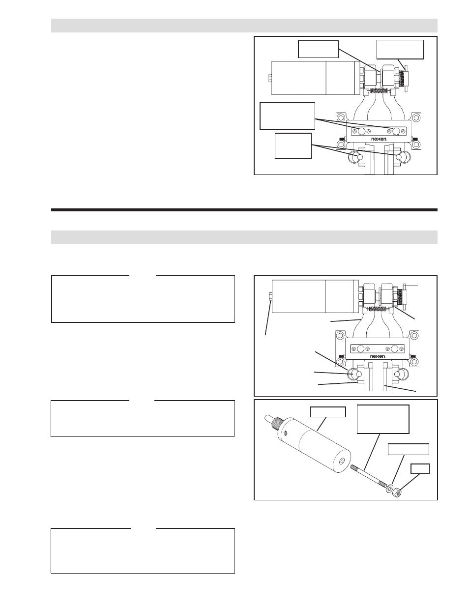
All pivot points on the BD Caliper Brake use self-lubricated
high PV Sleeve Bearings.
For tension control applications where the disc is held at elevated
temperatures for extended periods, use a light machine oil on
Sleeve Bearings (Items 14, 15 and 30) (See Figure 7).
The sliding spherical contact between the Adjustment Screw
(Item 8) and the spherical shaft end should be lubricated with
a molybdenum disulfide based grease (See Figure 7).
Adjustment
Screw (Item 8)
Sleeve
Bearing
(Item 15)
FIGURE 7
PARTS REPLACEMENT
FRICTION FACINGS
NOTE
When replacing Friction Facings, inspect the Friction
Disc for scoring or grooves. If necessary, the Friction
Disc may be turned. A total of 0.030'' [0.762 mm] may
be removed from each side of the Friction Disc before
it is necessary to replace the Friction Disc.
1.
Remove the Vent (Item 17) from the back of the Actuator
(See Figure 8).
2. Using the Nexen Manual Release Kit (Product No. 933596)
manually release the brake by inserting the Grade 5, 3/8-
16 x 9'' Threaded Rod into the back of the Actuator; then,
using a Flat Washer and Nut, tighten the Nut to release
the brake (See Figure 9).
NOTE
Two Belleville Disc Springs (Item 29) are compressed
between the Brake Arm (Item 2) and the Shoe (Item 3).
When the Shoe is removed, the Belleville Disc Springs
will fall free from the Brake Arms.
3. Remove Detent Pins (Item 16) to release Friction Facings
(Item 4), Shoes (Item 3), and Belleville Disc Springs
(Item 29) from Brake Arms (Item 2) (See Figure 8).
4. Remove Friction Facings (Item 4) from the Shoes (Item
3) by removing the old Machine Screws (See Figure 8).
5. Install new Friction Facings (Item 4) using new Machine
Screws (Item 18).
6. Tighten the Machine Screws (Item 18) to 8-12 Ft. Lbs.
[12‑15 N•m] torque.
NOTE
When reinstalling the Shoe (Item 3), first place the
Belleville Disc Springs (Item 29) into the recesses
provided in the Brake Arm (Item 2). The Belleville Disc
Springs should be inserted with their concave side
toward the Brake Arm.
2
8
12
17
16
29
3
FIGURE 8
Spherical
Shaft End
Sleeve
Bearing
(Item 14 and 30)
4
Flat Washer
Nut
Grade 5
3/8-16 x 9''
Threaded Rod
Actuator
FIGURE 9
7. Loosen adjustment screw Spanner Nut (Item 12) and back
out Adjustment Screw (Item 8) until the Friction Facings,
Shoes, and Belleville Disc Springs will slide back onto the
Brake Arms (Item 2) (See Figure 8).
8. Replace the Detent Pins (Item 16) (See Figure 8).
9. Perform Friction Facing adjustment (See
FRICTION
FACING CLEARANCE ADJUSTMENT).