Nexen 4K Hinge Top 845100 User Manual
Page 5
2
FORM NO. L-20014-L-0210
INSTALLATION
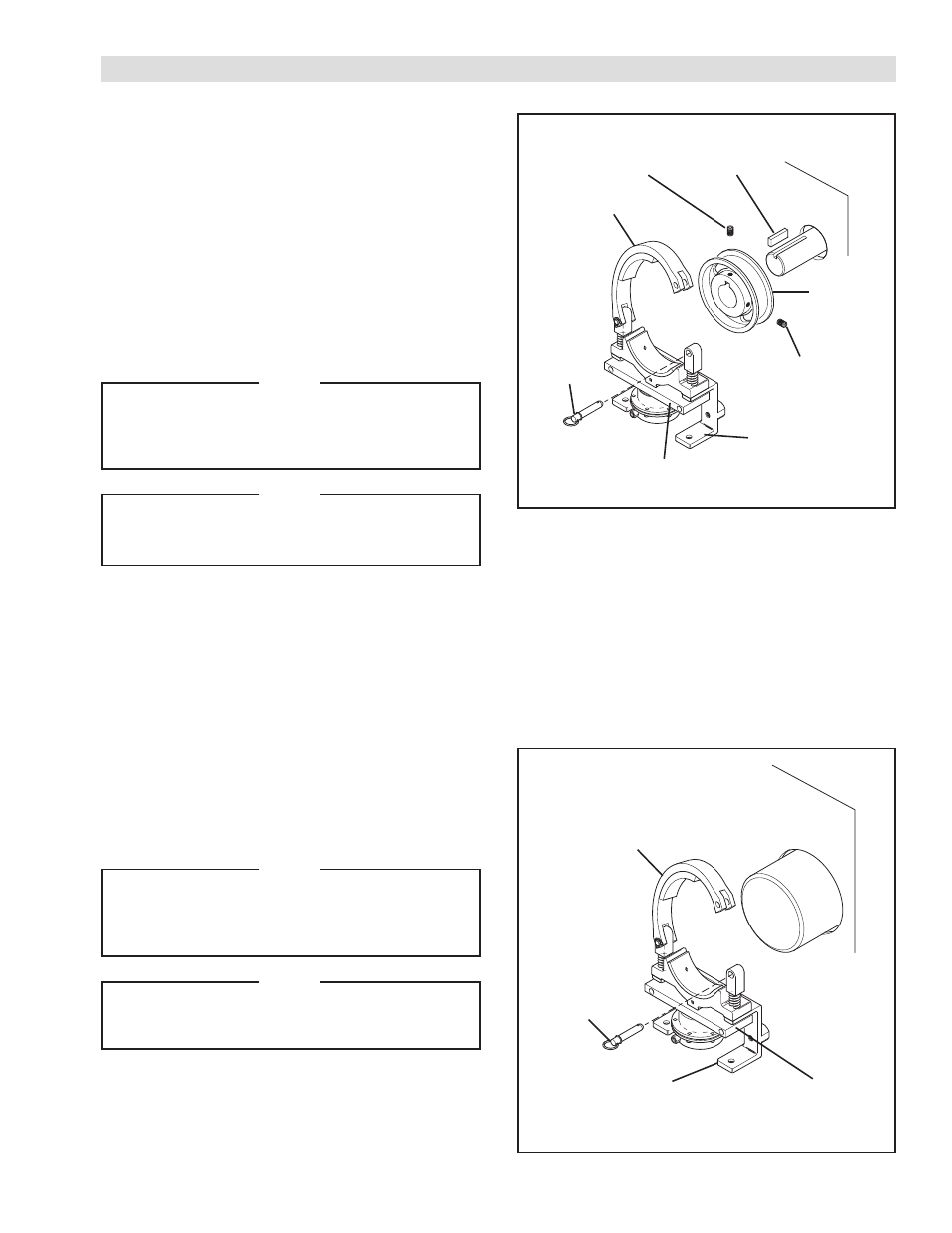
FIGURE 1
BRAKE WITHOUT OPTIONAL DRUM
REFER TO FIGURE 2.
1. Pull the Detent Pin (Item 29) and lift the hinged Fixed
Shoe (Item 1) to the open position.
NOTE
For maximum wear of hinged Fixed Shoe Friction
Facing (Item 3), the Self Centering Bracket (Item
14) should be touching the Base Bar (Item 4)
when mounting the Diaphragm Brake.
NOTE
Allow sufficient clearance between the Friction
Facings (Item 3) and the shaft to allow free
rotation of the shaft.
2. Position the Brake on the shaft with the Fixed Shoe
(Item 1) riding on the shaft and the Self Centering
Bracket (Item 14) mounted as low as possible.
3. Secure the Self Centering Bracket (Item 14).
FIGURE 2
Customer
Supplied Key
Customer
Supplied
Set Screw
Customer
Supplied
Set Screw
Detent Pin
(Item 29)
Fixed Shoe
(Item 1)
Self Centering
Bracket (Item 14)
Base Bar
(Item 14)
Optional
Drum
Fixed Shoe
(Item 1)
Base Bar
(Item 14)
Detent Pin
(Item 29)
Self Centering
Bracket (Item 14)
BRAKE WITH OPTIONAL DRUM
REFER TO FIGURE 1.
1. Insert a customer supplied Key onto the shaft.
2. Slide the optional Drum over the customer supplied
Key and onto the shaft.
3. Secure the optional Drum to the shaft using two
customer supplied Set Screws.
4. Pull the Detent Pin (Item 29) and lift the hinged Fixed
Shoe (Item 1) to the open position.
NOTE
For maximum wear of hinged Fixed Shoe Friction
Facing (Item 3), the Self Centering Bracket (Item
14) should be touching the Base Bar (Item 4)
when mounting the Diaphragm Brake.
NOTE
Allow sufficient clearance between the Friction
Facings (Item 3) and the optional Drum to allow
free rotation of the Drum.
5. Position the Diaphragm Brake on the optional Drum
with the Fixed Shoe (Item 1) riding on the Drum and
the Self Centering Bracket (Item 14) mounted as low
as possible.
6. Secure the Self Centering Bracket (Item 14).