Nexen FMCBE-875 801428 User Manual
Page 10
10
FORM NO. L-20150-V-1112
PARTS REPLACEMENT / FRICTION FACINGS
TABLE 2
MODELS 625, 875, 1125, AND 1375
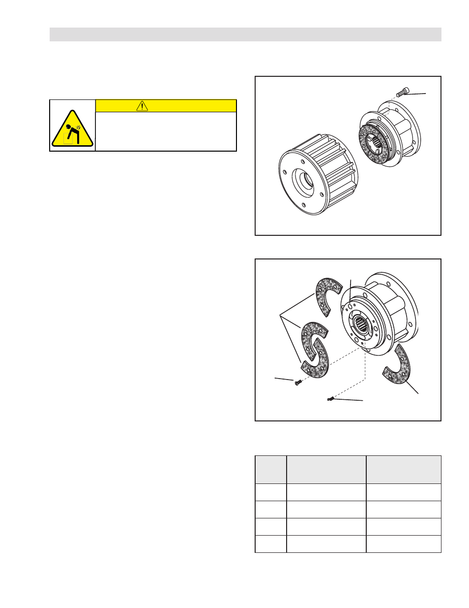
1. Remove the four Socket Head Cap Screws (Item 13)
and separate the two halves of the FMCBE (See Figure
8).
2. Remove the six old Flat Head Machine Screws (Item
7) and the first old split Friction Facing (Item 11) (See
Figure 9).
3. Align the holes in the Splined Disc (Item 9) with the Flat
Head Machine Screws (Item 7) that secure the second
split Friction Facing (Item 11) (See Figure 9).
4. Remove the six old Flat Head Machine Screws (Item
7 and the second old split Friction Facing (Item 11)
(See Figure 9).
5. Clean the friction surfaces and facing mounting surfaces
with fresh safety solvent.
6. Install the first new split Friction Facing (Item 11) and
new Flat Head Machine Screws (Item 7) (See Figure
9).
7. Tighten the six new Flat Head Machine Screws. See
Table 2 for torque values.
8. Install the second new split Friction Facing (Item 11)
and six new Flat Head Machine Screws (Item 7) (See
Figure 9).
9. Tighten the six new Flat Head Machine Screws. See
Table 2 for torque values.
10. Apply a drop of Loctite
®
242 to the threads of the four
Socket Head Cap Screws (Item 13) (See Figure 8).
11. Install and tighten the four Socket Head Cap Screws
(Item 13) securing the two halves of the FMCBE to the
recommended torque (See Figure 8 and Table 2).
FIGURE 8
13
FIGURE 9
11
11
7
9
7
FMCBE
Model
RECOMMENDED
TIGHTENING TORQUE
(ITEM13)
FACING SCREW
TORQUE (ITEM 7)
625
157 In. Lbs. [17.7 Nm]
26 In. Lbs. (2.9 Nm)
875
267 In. Lbs. [30.2 Nm]
26 In. Lbs. (2.9 Nm)
1125
267 In. Lbs. [30.2 Nm]
71 In. Lbs. (8.0 Nm)
1375
594 In. Lbs. [67.1 Nm]
71 In. Lbs. (8.0 Nm)
CAUTION
Some product assemblies can exceed
90 lbs. Use lifting aids and proper
lifting techniques when installing,
removing, or placing in service.