Parts replacement / ball bearing – Nexen FMCBE-875 801428 User Manual
Page 11
11
FORM NO. L-20150-V-1112
PARTS REPLACEMENT / BALL BEARING
NOTE: The following sections are arranged by model. Verify that you are in the correct section for your model.
13
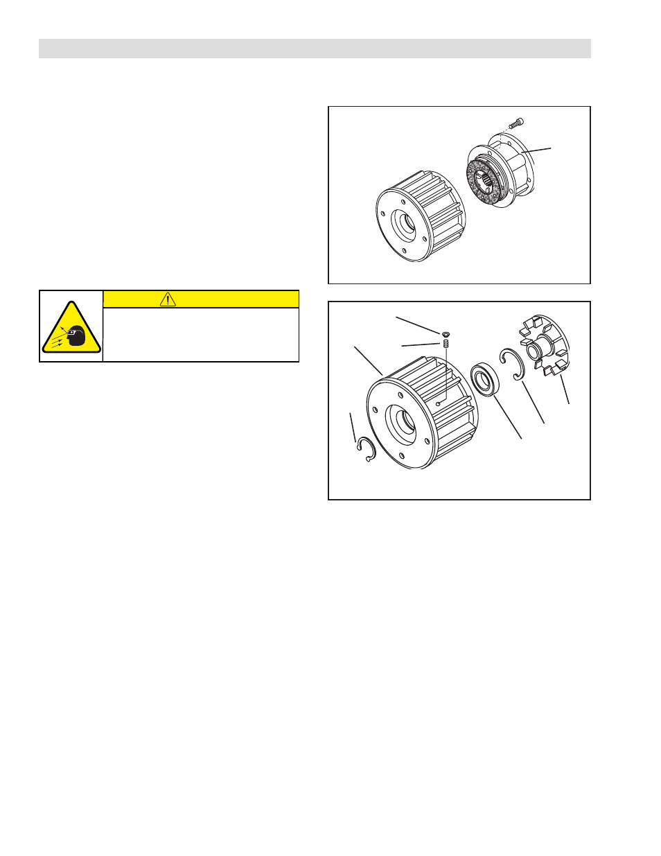
FIGURE 10
MODEL 625 HOUSING
NOTE: If an Input Unit is installed on the FMCBE, it must
be removed before servicing the FMCBE. Remove
Cap Screws and the Plug (Item 27) and loosen the
Set Screw (Item 26) to release the FMCBE from
the Input Unit (See Figure 11).
1. Remove the four Socket Head Cap Screws (Item 13)
and separate the two halves of the FMCBE (See Figure
10).
2. Remove the Plug (Item 27) and Set Screw (Item 26)
(See Figure 11).
3. Remove the Retaining Ring (Item 6) and press the
drive Disc (Item 4) out of Housing (Item 1) (See Figure
11).
4. Remove the Retaining Ring (Item 3) (See Figure 11).
5. Fully supporting the Housing (Item 1), press the old
Ball Bearing (Item 2) out of the Housing (See Figure
11).
NOTE: Do not reuse the bearing. Applying force on
inner bearing race to remove bearing held by
outer race causes damage to the bearing.
6. Clean the bearing bore of the Housing (Item 1) with
fresh safety solvent, making sure all old Loctite
®
residue
is removed (See Figure 11).
7. Apply an adequate amount of Loctite
®
680 to evenly
coat the outer race of the new Ball Bearing (Item 2)
(See Figure 11).
8. Carefully align the outer race of the new Ball Bearing
(Item 2) with the bore of the Housing (Item 1).
9. Supporting the Housing (Item 1) and pressing on the
outer race of the new Ball Bearing (Item 2), press the
new Ball Bearing into the Housing (See Figure 11).
10. Reinstall the Retaining Ring (Item 3) (See Figure 11).
27
26
2
3
4
FIGURE 11
1
6
11. Support the inner race of the new Ball Bearing (Item
2) and press the Drive Disc (Item 4) into the new Ball
Bearing (Item 2) and Housing (Item 1) (See Figure
11).
12. Reinstall the Retaining Ring (Item 6) (See Figure 11).
NOTE: If you are replacing all the Ball Bearings and
O-ring Seals in the FMCBE Model 625,
proceed with PARTS REPLACEMENT—
BEARINGS AND O-RING SEALS; otherwise,
proceed with next step.
13. Apply a drop of Loctite
®
242 to the threads of the four
Socket Head Cap Screws (Item 13) and secure the
two halves of the FMCBE together (See Figure 10).
14. Tighten the four Socket Head Cap Screws (Item 13)
to 10.5 Ft. Lbs. [14.2 Nm] torque (See Figure 10).
CAUTION
Working with spring loaded or tension
loaded fasteners and devices can cause
injury. Wear safety glasses and take the
appropriate safety precautions.