Nexen RSD250 964260 User Manual
Page 5
5
FORM NO. L-21179-D-1108
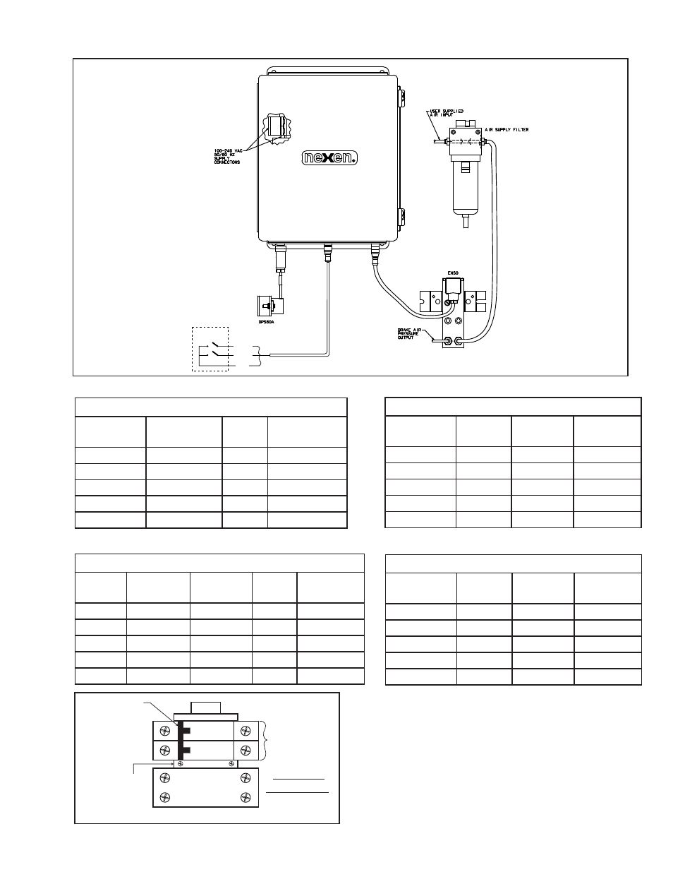
ELECTRICAL AND PNEUmATIC CONNECTIONS
Digital Inputs
Brown
White
Blue
Splice
Start/Stopped
User Supplied
Contacts
Figure 1
Table 1
Table 2
Table 3a
Circuit Breaker
L2
L1
Earth
Ground
ON/OFF
Power Switch
Figure 2
AC Power
Connections
RSD250E
Digital Inputs
Function
Cable wire
Cable
Pin
Receptacle
wire
Start/Stop
Brown
1
Brown
Splice
White
2
White
Common
Blue
3
Blue
None
Black
4
Black
Shield
Shield Drain
5
Green/Yellow
DPS60
Function
DSP60
Connector
Pin
Receptacle
wire
+ 12 VDC
Brown
1
Brown
DC Com
Blue
3
Blue
Output 1
Black
4
Black
Output 2
Orange
2
White
Shield
Drain
5
Gray
EN50
Function
DIN
Connector Cable wire
Cable
Pin
Receptacle
wire
+ Signal
1
Brown
1
Brown
- Signal
2
Blue
3
Blue
Ground
Ground
Black
4
Black
Shield
2
White
Shield
Shield
5
Gray
DPS60A
Function
DSP60A Connector
Pin
Receptacle
wire
+ 24 VDC
Green
1
Brown
DC Com
Brown
3
Blue
Output
White
4
Black
Not Used
Yellow
2
White
Shield
Shield
5
Gray
Table 3b