Nexen RSD250 964260 User Manual
Page 7
7
FORM NO. L-21179-D-1108
START/STOPPED SIGNAL SELECTION
The RSD250 determines the start/stopped state of a machine through the Start/Stopped Signal Input. The RSD250
was designed to accommodate many different types of machine state signals.
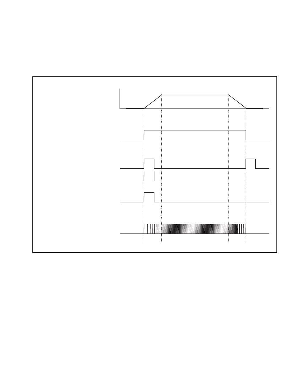
The following figure and descriptions detail the variations of Start/Stopped signals that the RSD250 accepts.
After choosing the appropriate signal, set the rotary switch on the RSD250 printed circuit board per Table 4.
(6) Encoder
(Pulses)
(5) Start Only
(Momentary)
(2) Start / Stopped
(Momentary)
(1) Start / Stopped
(Maintained)
0%
100%
Machine Speed
Pulse Time (t) must be > 100ms
-t-
Time
Figure 4
Start / Stopped Signal (maintained)
When the Start/Stopped input signal is maintained low, the RSD250 assumes the machine is stopped. When the
Start/Stopped input signal transitions to a maintained high, the RSD250 algorithm will begin adapting to account
for the roll’s diameter and inertia. The web must be in motion when this signal goes high otherwise the Adaptive
Gain will increase to maximum. After the Start/Stopped signal transitions back to low, the Adaptive Gain will stop
adapting and remain a constant value.
Start / Stopped Signal (momentary)
When the Start/Stopped input signal pulses high, the RSD250 algorithm will begin adapting to account for the
roll’s diameter and inertia. The web must be in motion when this signal goes high otherwise the Adaptive Gain will
increase to maximum. After the Start/Stopped signal pulses high a second time, the Adaptive Gain will stop adapt-
ing and remain a constant value, because the RSD250 assumes the machine has stopped.
S
taRt
/S
toppED
S
ignal
D
EScRiptionS