Nexen SC100 964420 User Manual
Page 10
FORM NO. L-21163-C-0808
10
16
15
14
13
12
11
9
10
+
+
+
+
16
15
14
13
12
11
9
10
+
+
Channel 1
Input
16
15
14
13
12
11
9
10
+
+
+
+
16
15
14
13
12
11
9
10
+
+
+
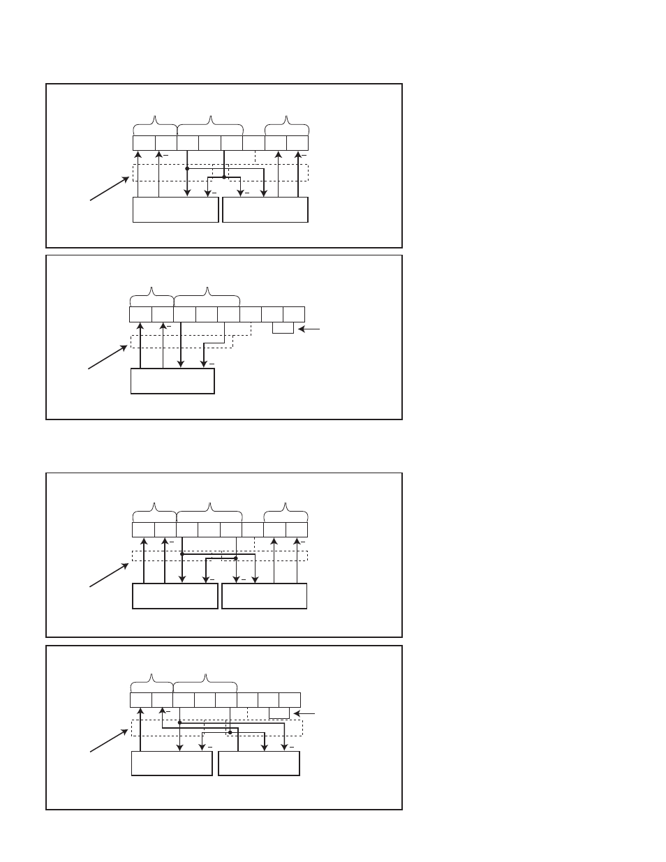
GENERIC SENSOR CONNECTION DIAGRAMS
S
INGLE
-E
NDED
O
UTPUT
S
ENSORS
Figure 12
Dual Sensor Wiring
Figure 13
Single Sensor Wiring
D
IFFERENTIAL
O
UTPUT
S
ENSORS
Figure 14
Full Bridge Sensor Wiring
Figure 15
Half Bridge Sensor Wiring
Excitation
Voltage
Add jumper wire
Channel 1
Input
No. 1 Sensor
No. 2 Sensor
Shield
Excitation
Voltage
Channel 2
Input
No. 1 Sensor
No. 2 Sensor
Shield
Excitation
Voltage
Channel 2
Input
Channel 1
Input
No. 1 Sensor
No. 2 Sensor
Shield
Channel 1
Input
Excitation
Voltage
No. 1 Sensor
Shield
Add jumper wire
NOTE: Figures 12, 13, 14 & 15
assume a normal implementation
where an increase in sensor
measurement corresponds to
an increase in voltage. For
implementations where an increase
in sensor measurement corresponds
to a decrease in output voltage, the
sensor signal wires must be inverted.
An increase in sensor measurement
must correspond to an increase in
sensor voltage.
*See Note.
*See Note.
*See Note.
*See Note.