Sc100, Power supply connections – Nexen SC100 964420 User Manual
Page 7
7
FORM NO. L-21163-C-0808
SC100
9
10
11
12
13
14
15
16
8
7
6
5
4
3
2
1
+
+
Isolated
Output 2
Isolated
Output 1
+
Second Power
Supply
+
Power Supply
Z1
S1
Z2
S2
IND
LO
LO
SUM
OUT
MODE
HI
CH1
GAIN
HI
CH2
GAIN
CH2
OUT
CH1
OUT
PWR
VEX
V
V
SC100
9
10
11
12
13
14
15
16
8
7
6
5
4
3
2
1
+
Output 2
+
Output 1
+
Power Supply
Z1
S1
Z2
S2
IND
LO
LO
SUM
OUT
MODE
HI
CH1
GAIN
HI
CH2
GAIN
CH2
OUT
CH1
OUT
PWR
VEX
V
V
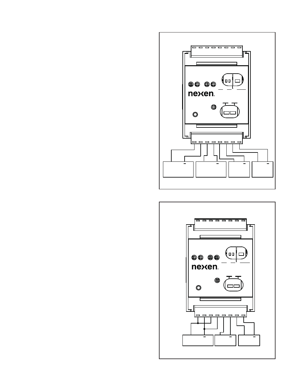
Power Supply Connections for Isolated Outputs
Power Supply Connections for Non-Isolated Outputs
POWER SUPPLY CONNECTIONS
Figure 4
Figure 5
Isolated Power Supply connections are available so that
the Control Outputs are isolated from the input circuitry.
When using Isolated Control Outputs, a second 15-24
VDC power supply is needed (See Figure 4). This
setup is most commonly used to prevent the mixing
of power supply commons together when connecting
analog control outputs to a motor drive (Refer to
SPECIFICATIONS).
If Isolated Control Outputs are not needed, the Isolated
+VDC and ISO Common must be connected to +24
VDC and DC common inputs, respectively (See Figure
5).