Nexen SC100 964420 User Manual
Page 8
FORM NO. L-21163-C-0808
8
16
15
14
13
12
11
9
10
+
G
W
R
B
Excitation
Voltage
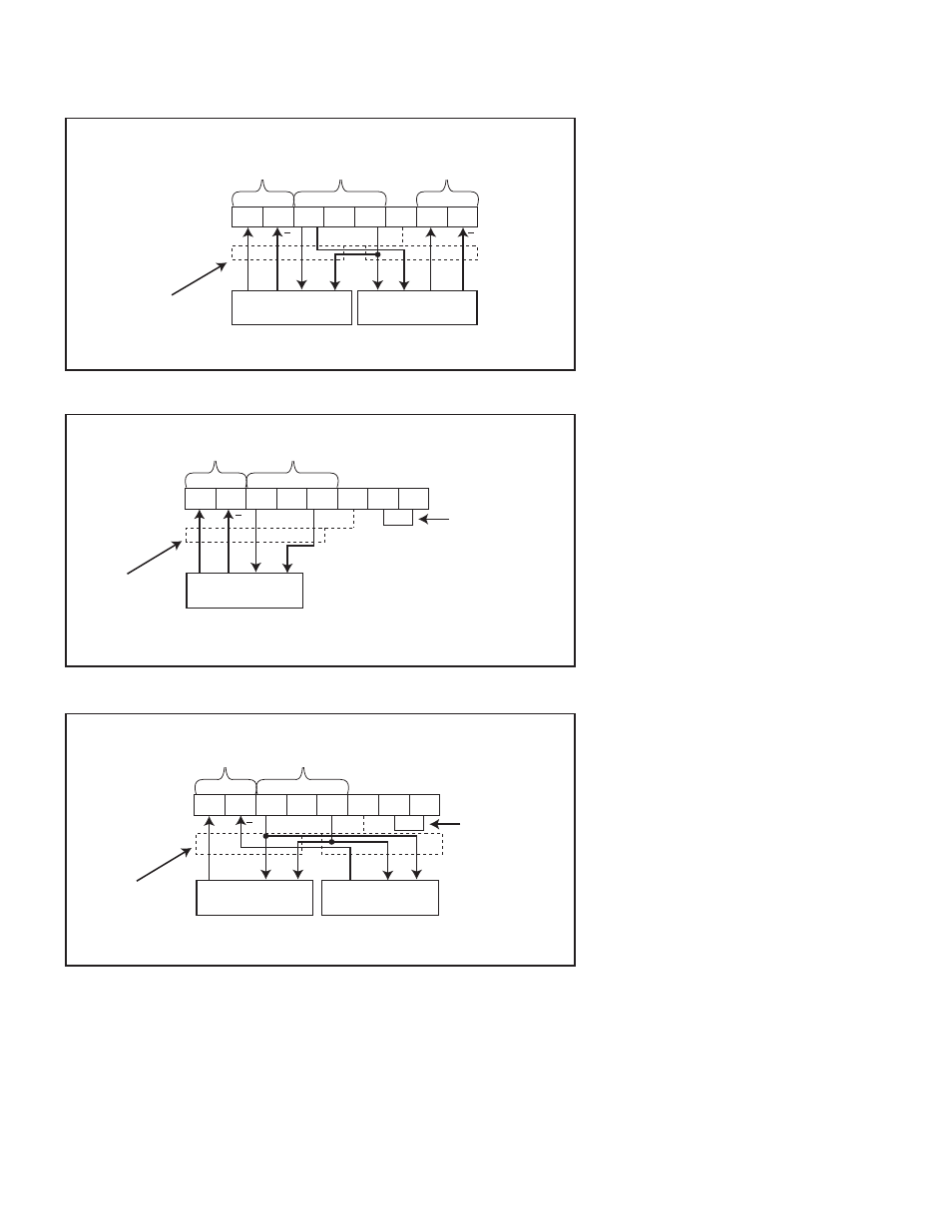
NEXEN SENSOR CONNECTIONS DIAGRAMS
W
EB
T
ENSION
S
ENSORS
Figure 6
Dual MB Sensor Wiring
16
15
14
13
12
11
9
10
+
+
G
W
R
B
B
W
G
R
Excitation
Voltage
Channel 2
Input
Channel 1
Input
No. 1 Sensor
No. 2 Sensor
Shield
Figure 7
Single MB Sensor Wiring
Channel
1 Input
No. 1 Sensor
Shield
Add jumper wire
16
15
14
13
12
11
9
10
+
W
R
B
W
R
B
Figure 8
SW Sensor Wiring
Excitation
Voltage
Add jumper wire
Channel 1
Input
No. 1 Sensor
No. 2 Sensor
Shield
NOTE: Figures 6 & 7 are for use
in normal wrap implementations.
Normal wrap is defi ned as an
increase in tension measurement
corresponds with increase of
load cell force. For reverse wrap
implementations, where an increase
in tension measurement corresponds
to a decrease in load cell force, the
White and Green wires must be
inverted. An increase in tension must
corresond to an increase in voltage
at the sensor input.
*See Note.
*See Note.