Information, Figure 1–3 – Altera Power Delivery Network User Manual
Page 8
1–4
Chapter 1: Power Delivery Network (PDN) Tool User Guide
Setting Up the PDN Tool
Power Delivery Network (PDN) Tool User Guide
© March 2009
Altera Corporation
For more information on the Decap Selection tab, refer to
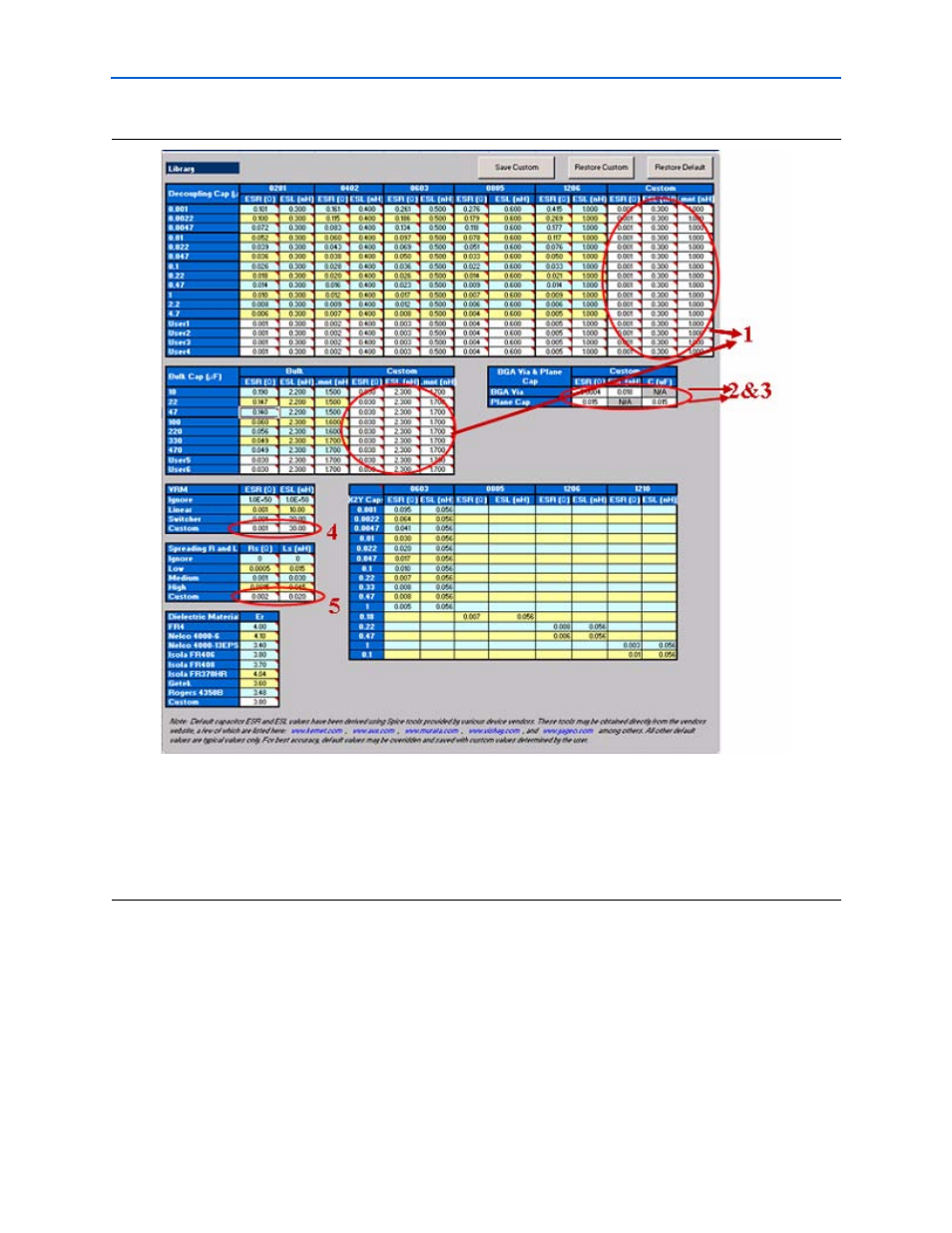
Figure 1–3. Library Tab
Notes to
The numbers in
correspond to the follwing steps 1, 2, 3, 4, 5.
(1) Enter the ESR, ESL, and L
mount
values for the capacitors under the Custom field.
(2) Enter the effective BGA via (loop) parasitics for the power supply being decoupled.
(3) Enter the plane capacitance seen by the power/ground plane pair on the board for the power supply under Plane Cap.
(4) Enter the VRM parasitics, if available, under the Custom row.
(5) Enter the effective spreading inductance seen by the decoupling capacitors in the Custom row.