General user input/output, User push buttons, General user input/output –26 – Altera 100G Development Kit, Stratix V GX Edition User Manual
Page 34: User push buttons –26
2–26
Chapter 2: Board Components
General User Input/Output
100G Development Kit, Stratix V GX Edition
August 2012
Altera Corporation
Reference Manual
General User Input/Output
This section describes the user I/O interface to the FPGA and MAX II CPLD EPM2210
System Controller, including the following elements:
■
User push buttons
■
User DIP switches
■
User LEDs
■
LCD
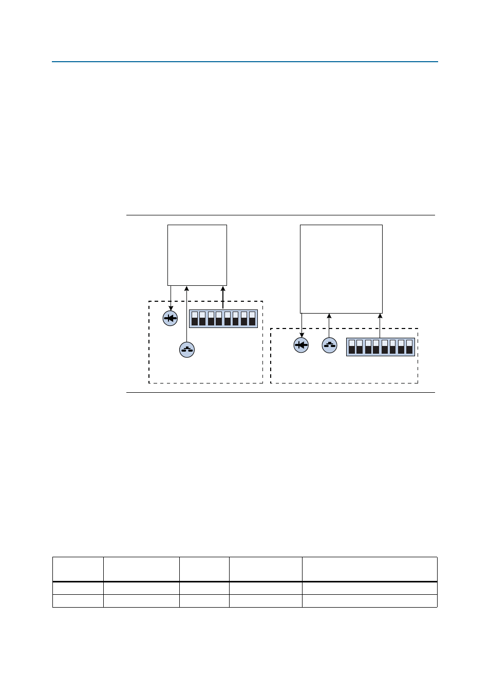
shows the general user I/O connection.
User Push Buttons
The development board includes seven push buttons for user-defined logic input and
one CPU reset. For information on the CPU reset push button, refer to
Board references S2 to S4 and S9 to S12 are push buttons that allow you to interact
with the MAX II CPLD device and the Stratix V GX device. When you press the
switch and hold it down, the device pin is set to logic 0. When you release the switch,
the device pin is set to logic 1. There is no board-specific function for these general
user push buttons.
lists the user push button schematic signal names and their corresponding
Stratix V GX device pin numbers.
Figure 2–8. General User I/O Connection
User DIP
Switch
4 User
Push
Buttons
8 FPGA
User LEDs
MAX II
CPLD
Stratix V GX
FPGA
User DIP
Switch
3 User Push
Buttons
4 User
LEDs
Table 2–15. User Push Button Signal Names and Functions (Part 1 of 2)
Board
Reference
Schematic
Signal Name
I/O Standard
Stratix V GX Device
Pin Number
Description
S2
USER_PB2
2.5-V CMOS
—
MAX II user push button
S3
USER_PB1
2.5-V CMOS
—
MAX II user push button