Act multi channel wireless receiver, Parts name and functions – MIPRO act-707f User Manual
Page 3
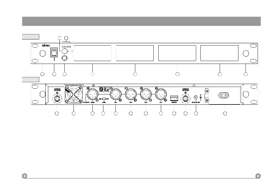
Front Panel:
Rear Panel:
(1)
FrontAntennaAInputConnector: Allows an optional rear-to-frontAntennakit forfront antenna
placement.
(2)
Power Switch & Indicator: When switchisturnedon, red indicator illuminates todenote normal
power status.
(3)
HeadphoneJack:Toconnecttoastereoheadphone to monitor outputsignals.
(4)
Headphone Volume Control and Module Selector: Pushes the knob to selectthe module you
would like tomonitor; turns the knob toadjust the volume ofthestereoheadphone.
(5)
Module Indicator: Points out selectedmonitoringmodule
(6)
Receiver Module 1: First Receiver ModuleSlot[Ch. 1 ]
(7)
Receiver Module 2: SecondReceiver Module Slot [ C h . 2 ]
(8)
Receiver Module 3:Third Receiver Module Slot[Ch. 3 ]
(9)
Receiver Module 4: Fourth Receiver Module Slot[Ch. 4]
(10)
Front A n t e n n a B I n p u t C o n n e c t o r : Allows an optional rear-to-frontAntenna kitforfrontantenna
placement.
2
2. PARTS NAME AND FUNCTIONS
ACT MULTI CHANNEL WIRELESS RECEIVER
(11)
Rear Antenna B input Connector: B Antennaconnectorcanbeinstalledwithantenna directly and
provides power for antenna booster.
(12)
Heat Sink: Pleasekeepit adequatelyventilated.
(13)
Mixed AFOutput Socket: A balanced output socketformixedAFsignalsfromall installed
modules;2 outputlevelsto switch from.
(14)
Mixed AFOutput Level Switch: Canswitch theoutput t o M I C o r A U X l e v e l .
(15)
Output Socket forModule 4: The balancedoutput socket for fourth receiver module. [Ch.4]
(16)
Output Socket forModule 3: The balancedoutput socket for thirdreceivermodule. [Ch. 3]
(17)
O utput Socket forModule 2: The balancedoutput socket forsecondreceivermodule. [Ch. 2]
(18)
Output Socket forModule 1: The balancedoutput socket for firstreceivermodule. [Ch. 1]
(19)
Computer Network InterfaceConnector:Networksocket to connect to the computerized system-
monitoring program.
(20)
RearAntennaAinput Connector:AAntennaconnector can be installed with antennadirectly and
provides power for antenna booster.
(21)
DCInputSocket: Theinput socket for 12 VoltDC power. Pleasenote that the polarity of the
central pin in the socketispositive (+).
(22)
A C P o w e r S o c ket: Theinput socketforAC power. UsesAC powerranging from 9 0 A C V t o 2 6 4
ACVwithout changing any application.
3
ACT MULTI CHANNEL WIRELESS RECEIVER
(Fig.1)
(Fig.2)
9
10
7
8
2
3
4
5
6
C H 1
C H 2
CH3
HEADPHONE
POWER
CH4
CH3
CH2
CH1
PUSH
ACT-707
CH4
1
0
1
11
12
14
13
16
15
17
18
20
19
21
22