MIPRO act707hm(2ce141b) User Manual
Page 2
6.
Color Rear Housing Protecting On-off switch
structure a n d preventing users free from switching
power off accidentally.
7.
ACT Signal Receptor: Receiving ACT signal and
adjusting frequency automatically.
8.
Battery Compartment: Designed to accommodate
two 1.5V(AA) batteries.
9.
LCD Panel: Display group
channel
error code a n d
battery meter status.
10.
Power Switch: Sliding the switch for power "ON" or
"OFF".
﹕
、
、
1.
Top Grille
Designed to protect microphone capsule.
2.
Internal Foam Screen ofUpper Grille: It is inclosed
inside the protective pouch of microphones for
advancing to eliminate "pop" noise in special
occasion.
3.
Internal Foam Screen ofLower Grille And Capsule
Module : Internal foam screen of lower grille is
designed toprotect capsule module which transfer
voice into audio frequency.
﹕
4.
Upper Housing: Designed to connect to grille,
capsule module and accommodate emission PCB
and battery compartment
5.
Lower Housing: Designed to protect battery
compartment and batteries.
Finely crafted and ergonomically
designed ACT-707HM adapts magnesium alloy
housing, LCD panel, and high-efficient
transmitting circuit design with low spurious
showcases MIPRO's professional style.
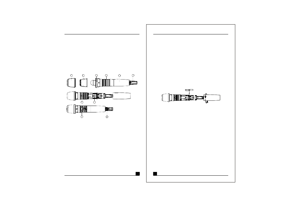
2. BATTERY INSTALLATIONS
1
2
1
8
2
3
4
6
7
9
10
5
Wireless Microphone
Wireless Microphone
1. PARTS NAME AND FUNCTIONS
(Fig.1)
(Fig.2)
1.
Unscrew housing (5) in counter-clockwise direction.
2.
Insert two1.5V(AA)batteries correctly into the battery
compartment ( 8 ) w i t h the positive pole (+) points at the
microphone capsule. Then, screw the housing (5)back
to microphone asshownin fig. 2.
PS:
When the m icrophoneis notin use:
Make sure thepowerof the microphone isoff. If the
microphone will not beusedfor some time, please
remove thebatteries from the battery compartment t o
avoid battery leakageand result in damaged battery
springs and circuit. Ifarechargeable battery was
used, take it out and recharge it.