Handheld wireless microphone, Bodypacks transmitter – MIPRO ma101a User Manual
Page 7
1 0
11
10
1
2
3
5
8
7
4
6
9
Handheld Wireless Microphone
Undernormal operation, when receiver and transmitter are paired together
tosetfrequency, microphone indicator (3) will remainoffafter ACT s e t u p t h e
frequency. However, if indicator (3) is flashing, it means receiver and
transmitter are n o t inthesamefrequency band. Please check thestickers on
transmitter andreceiver to observe if they are sharingthesamefrequency
bands.
(Fig.2)
2. BATTERY INSERTION
3. OPERATING INSTRUCTIONS
1.
Unscrew battery c a p i n a counter-clockwise direction (7).
2.
Insert a 9V battery intothebatterycompartmentaccording to the correct
polarity asshown in Fig.2. The moment the battery touches the terminals,
the indicator willflash briefly (7). This means thepolarity is correct.
However, if no flash occurs, this indicateswronginsertion or that the
battery is dead.Pleasere-insert thebattery according to its correct
polarity orexchange it for a fresh battery.
1.
When microphone is switched on:
2.
During Usage:
3.
When themicrophone i s n o t in use:
When thepowerisswitchedon,theindicatorwill flashbrieflyindicating
normal operation.
T h e A F L E D indicator on the receiver willilluminate accordingto the
audio signal strength from themicrophone.
Make surethat you turn off the microphone afteruse toextend the
battery life. Remove the battery from the battery compartment if
microphone is not to be used a g a i n f o r some time. If a r echargeable
battery was used, take it out and recharge i t.
4. CAUTIONS
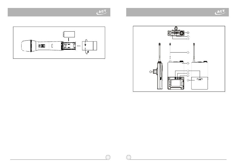
Bodypacks Transmitter
1. PARTS NAMES AND FUNCTIONS
(Fig.1)
1.
AF InputJack: Connects to e ither lavaliere or headset m icrophone. (See
5waysofconnection o n A F I n p u tConnections)
2.
Power Switch: Switch toONposition for operation. Switch toOFFposition
when not in use.
3.
Battery Status Indicator: Indicates thepower on / off and battery status.
(a) When power switch is turned on: TheLEDindicator flashes briefly,
indicating normal battery status.
(b) When RED light illuminates at either power o n o r d u r i n g u s a g e : T h e
battery level is low, therefore, a new battery replacement is thus
necessary.
4.
Transmitting Antenna: 1/ 4
transmitting antenna.
5.
Transmitter Housing: Packages thePCBandbattery.
6.
ACT Signal Receptor:ReceivingACTsignal and adjusting frequency
automatically.
7.
Gain Control: Adjusts thedesirous input gain.
8.
GT/MT Level Select Switch: Switch GT position forelectric guitar usage
and "Line In". Gain Control is irrelevant for "GT". Switch to " M T " f o r
condenser microphone or wired microphone. Gain Control works in"MT"
for input sensitivity adjusting.
λ