Connecting the power supply, Connecting the motors, Connecting the power supply connecting the motors – Applied Motion 2035XD User Manual
Page 6: Programmable output, 2035xd
-6-
Connecting the Power Supply
If you need information about choosing a power supply, please read Choosing a
Power Supply located on page 13 of this manual. The PS430 from Applied Motion
Products is a good supply for this drive.
If your power supply does not have a fuse on the output or some kind of short
circuit current limiting feature you need to put a 4 amp fast acting fuse between the
drive and power supply. Install the fuse on the + power supply lead.
Connect the motor power supply "+" terminal to the driver terminal labeled "+
VDC". Connect power supply "-" to the drive terminal labeled "VDC-". Use no
smaller than 20 gauge wire. Be careful not to reverse the wires. Reverse connection
will destroy your driver, void your warranty and generally wreck your day.
Connecting the Motors
Warning: When connecting a motor to the driver, be sure that the motor
power supply is off. Secure any unused motor leads so that they can't
short out to anything. Never disconnect the motor while the drive is
powered up. Never connect motor leads to ground or to a power supply!
You must now decide how to connect your
motor to the drive.
Four lead motors
Four lead motors
Four lead motors
Four lead motors
Four lead motors can only be connected one
way. Please follow the sketch at the right.
Six lead motors
Six lead motors
Six lead motors
Six lead motors
Six lead motors can be connected in series or
center tap. In series mode, motors produce
more torque at low speeds, but cannot run as
fast as in the center tap configuration. In
series operation, the motor should be operated at 30% less than rated current to
prevent overheating. Wiring diagrams for both connection methods are shown on
the next page. NC means not connected to anything.
A+
A–
B+
B–
4
lead
motor
Red
Blue
Yellow
White
4 Leads
+ VDC –
motor
supply
12-35 VDC
+
–
fuse
-11-
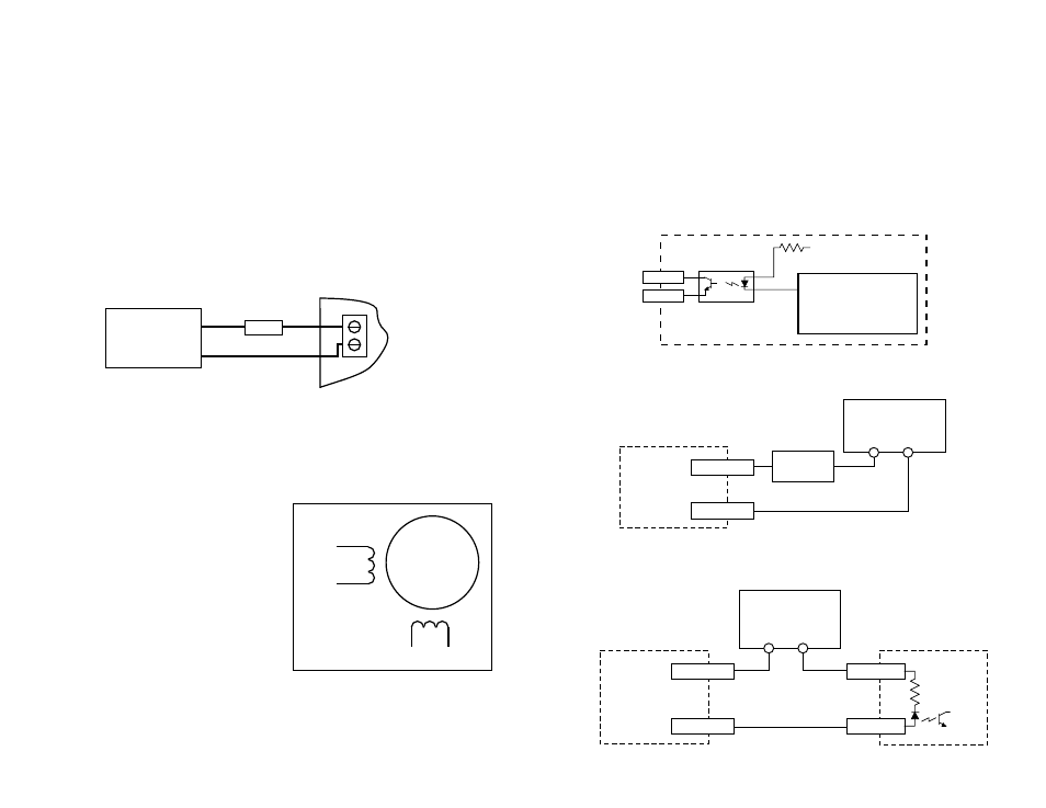
Programmable Output
The programmable output can be used to drive an LED, relay or the input of another
electronic device like a PLC or counter. The “+” (collector) and “-” (emitter) termi-
nals of the phototransistor are available at the connector. This allows you to
configure the output for current sourcing or sinking. Diagrams of each type of
connection are shown below.
Do not connect the output to more than 30VDC.
The current through the output terminals must not exceed 20 mA.
Schematic Diagram of Output Circuit
Sinking Output
Sourcing Output
2035XD
OUT-
OUT+
5-24 VDC
Power Supply
+
–
Load
330
+5V
OUT1–
OUT1+
Optoisolator
NEC PS2501
or equiv.
processor
inside 2035XD
PLC
COMMON
INPUT
2035XD
OUT-
OUT+
5-24 VDC
Power Supply
+
–