Step and direction signals, Step and direction signals run/stop signals – Applied Motion 2035XD User Manual
Page 8
-8-
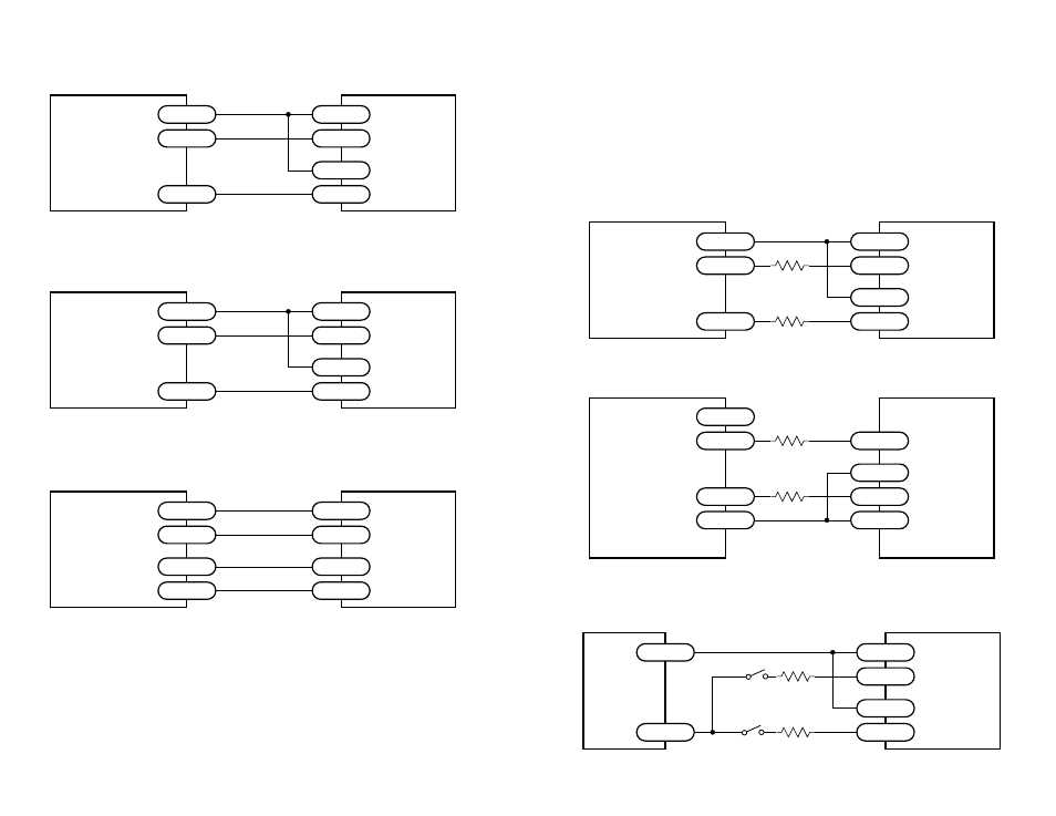
Step and Direction Signals
Connecting to Indexer with Sinking Outputs
(includes Applied Motion Si-1 Indexer)
2035XD
Drive
+5V OUT
DIR+
DIR
DIR-
STEP+
STEP
STEP-
Indexer
with
Sinking
Outputs
Connecting to Indexer with Differential Outputs
(Many High Speed Indexers have Differential Outputs)
2035XD
Drive
DIR+
DIR+
DIR-
DIR-
STEP+
STEP-
STEP+
STEP-
Indexer
with
Differential
Outputs
Connecting to indexer with Sourcing Outputs
2035XD
Drive
COM
DIR-
DIR
DIR+
STEP-
STEP
STEP+
Indexer
with
Sourcing
Outputs
-9-
Run/Stop Signals
Most PLCs, don't use 5 volt logic. You can connect signal levels as high as 24
volts to the 2035XD if you add external dropping resistors to the STEP and DIR
inputs, as shown below.
• For 12 volt logic, add 820 ohm, 1/4 watt resistors
• For 24 volt logic, use 2200 ohm, 1/4 watt resistors
Connecting to PLC with Sinking (NPN) Outputs
(Most PLC's use 24 volt logic)
2035XD
Drive
+12-24V
DIR+
DIR
DIR-
STEP+
STEP
STEP-
PLC
with
Sinking
Outputs
R
R
Connecting to PLC with Sourcing (PNP) Outputs
(Most PLC's use 24 volt logic)
2035XD
Drive
+12-24V
GND
DIR-
OUT1
DIR+
STEP-
OUT2
STEP+
PLC
with
Sourcing
Outputs
R
R
Using Mechanical Switches to Control Run/Stop and Direction
2035XD
Drive
+
DIR+
DIR-
STEP+
-
STEP-
+24VDC
Power
Supply
2200
2200
direction switch
run/stop switch
(closed=run)