Applied Motion 3540M User Manual
Page 7
Supply
R
Supply
R
Supply
R
Voltage
Ohms
Voltage
Ohms
Voltage
Ohms
12
1200
21
3000
30
4700
15
1800
24
3600
33
5100
18
2400
27
4200
35
5600
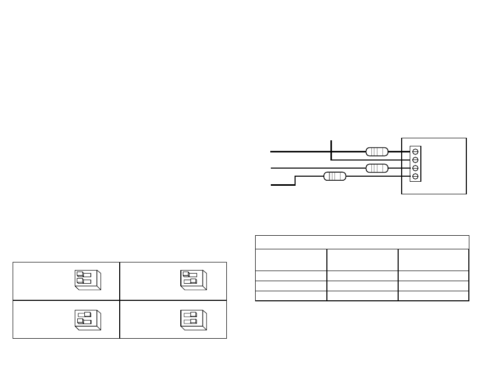
Table I: External Dropping Resistors
R
R
3540 M
drive
STEP +5 DIR EN
R
-7-
-10-
INPUT SIGNALS
+V (12-42 volts DC)
STEP
DIR
EN
Note: DIR signal is only required for bidirectional motion.
EN signal is only required to shut off motor current.
Both inputs can be left open if not needed.
Microstepping
Most step motor drives offer a choice between full step and half step resolutions. In
most full step drives, both motor phases are used all the time. Half stepping divides
each step into two smaller steps by alternating between both phases on and one
phase on. Microstepping drives like the 3540 M precisely control the amount of
current in each phase at each step position as a means of electronically subdividing
the steps even further. The 3540 M offers a choice of half step and 3 microstep
resolutions. The highest setting divides each full step into 64 microsteps, providing
12,800 steps per revolution when using a 1.8˚ motor.
In addition to providing precise positioning and smooth motion, microstep drives
can be used to provide motion in convenient units. When the drive is set to 2000
steps/rev (1/10 step) and used with a 5 pitch lead screw, you get .0001 inches/step.
Setting the step resolution is easy. Look at the dip switch on the 3540 M. Next to
switches 2 and 3, there are labels on the printed circuit board. Each switch has two
markings on each end. Switch 2 is marked 1/5, 1/10 at one end and 1/5, 1/64 at
the other. Switch 3 is labeled 1/2, 1/5 and 1/10, 1/64. To set the drive for a
resolution, push both switches toward the proper label. For example, if you want
1/10 step, push switch 2 toward the 1/10 label (to the left) and push switch 3 toward
1/10 (on the right).
Please refer to the table below and set the switches for the resolution you want.
400
STEPS/REV
(HALF)
1000
STEPS/REV
(1/5)
2000
STEPS/REV
(1/10)
12800
STEPS/REV
(1/64)
23
1/2
1/10
1/5
1/2
23
1/2
1/10
1/5
1/2
1/5
1/64
1/10
1/64
1/5
1/64
1/10
1/64
23
1/2
1/10
1/5
1/2
23
1/2
1/10
1/5
1/2
1/5
1/64
1/10
1/64
1/5
1/64
1/10
1/64
We have included the proper resistor (680 ohms) within the drive for 5 volt
operation. Therefore, if your logic voltage is 5 volts, you do not need to add
resistors externally.
If your logic voltage is higher than five volts, you must add a resistor in series with
each signal that you use (STEP, DIR and EN). The recommended wiring diagram is
shown below. Table I lists the appropriate resistor value to use for a given power
supply voltage. 1/4 watt or larger resistors should be used.
Please take care not to reverse the wiring, as damage to the LEDs will
result rendering the drives inoperable. Check your wiring carefully
before turning on the power supply!