Setting phase current – Applied Motion 3540M User Manual
Page 8
Step
A+
A-
B+
B-
0
1
2
3
4
5
6
7
8
DIR=1
cw
DIR=0
ccw
Step 0 is the Power Up State
Step Table
(half stepping)
-8-
-9-
0.1
0.2
0.4
0.8
1.6
56789
0.4
AMPS/
PHASE
0.1
0.2
0.4
0.8
1.6
0.5
AMPS/
PHASE
0.1
0.2
0.4
0.8
1.6
0.6
AMPS/
PHASE
0.1
0.2
0.4
0.8
1.6
0.7
AMPS/
PHASE
0.1
0.2
0.4
0.8
1.6
0.8
AMPS/
PHASE
0.1
0.2
0.4
0.8
1.6
0.9
AMPS/
PHASE
0.1
0.2
0.4
0.8
1.6
1.0
AMPS/
PHASE
0.1
0.2
0.4
0.8
1.6
1.1
AMPS/
PHASE
0.1
0.2
0.4
0.8
1.6
1.2
AMPS/
PHASE
0.1
0.2
0.4
0.8
1.6
1.3
AMPS/
PHASE
0.1
0.2
0.4
0.8
1.6
1.4
AMPS/
PHASE
0.1
0.2
0.4
0.8
1.6
1.5
AMPS/
PHASE
0.1
0.2
0.4
0.8
1.6
1.6
AMPS/
PHASE
0.1
0.2
0.4
0.8
1.6
1.7
AMPS/
PHASE
0.1
0.2
0.4
0.8
1.6
1.8
AMPS/
PHASE
0.1
0.2
0.4
0.8
1.6
1.9
AMPS/
PHASE
0.1
0.2
0.4
0.8
1.6
2.0
AMPS/
PHASE
0.1
0.2
0.4
0.8
1.6
2.1
AMPS/
PHASE
0.1
0.2
0.4
0.8
1.6
2.2
AMPS/
PHASE
0.1
0.2
0.4
0.8
1.6
2.3
AMPS/
PHASE
0.1
0.2
0.4
0.8
1.6
2.4
AMPS/
PHASE
0.1
0.2
0.4
0.8
1.6
2.5
AMPS/
PHASE
0.1
0.2
0.4
0.8
1.6
2.6
AMPS/
PHASE
0.1
0.2
0.4
0.8
1.6
2.7
AMPS/
PHASE
0.1
0.2
0.4
0.8
1.6
2.8
AMPS/
PHASE
0.1
0.2
0.4
0.8
1.6
2.9
AMPS/
PHASE
0.1
0.2
0.4
0.8
1.6
3.0
AMPS/
PHASE
0.1
0.2
0.4
0.8
1.6
3.1
AMPS/
PHASE
0.1
0.2
0.4
0.8
1.6
3.2
AMPS/
PHASE
0.1
0.2
0.4
0.8
1.6
3.3
AMPS/
PHASE
0.1
0.2
0.4
0.8
1.6
3.4
AMPS/
PHASE
0.1
0.2
0.4
0.8
1.6
3.5
AMPS/
PHASE
0.1
0.2
0.4
0.8
1.6
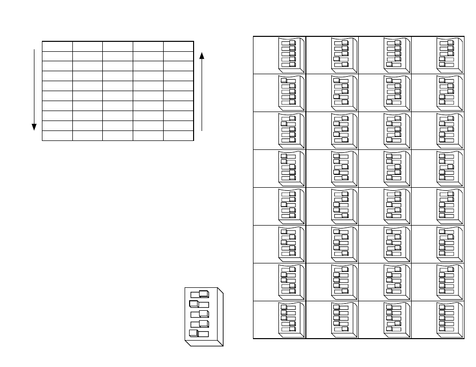
Current Setting Table
56789
56789
56789
56789
56789
56789
56789
56789
56789
56789
56789
56789
56789
56789
56789
56789
56789
56789
56789
56789
56789
56789
56789
56789
56789
56789
56789
56789
56789
56789
56789
56789
Setting Phase Current
Before you turn on the power supply the first time, you need to set the driver for the
proper motor phase current. The rated current is usually printed on the motor label.
The 3540 M drive current is easy to set. If you wish, you can learn a simple formula
for setting current and never need the manual again. Or you can skip to the table on
the next page, find the current setting you want, and set the DIP switches according
to the picture.
Current Setting Formula
Locate the bank of tiny switches near the motor connector. Four of the switches
have a value of current printed next to them, such as 0.4 and 0.8. Each switch
controls the amount of current, in amperes (A), that its label indicates. There is
always a base of current of 0.4 A. To add to that, slide the appropriate switches
toward their labels on the PC board. You may need your small screwdriver for this.
Example
Suppose you want to set the driver for 2.2 amps per
phase. You need the 0.4 A base current plus another 1.6
and 0.2 A.
2.2 = 0.4 + 1.6 + 0.2
Slide the 1.6 and 0.2 A switches toward the labels as
shown in the figure.
open
+
+
+
open
–
–
–
open
open
–
–
–
open
+
+
+
open
+
+
open
–
–
–
open
+
+
–
–
open
+
+
+
open
–
–