Choosing a power supply, Connecting the power supply – Applied Motion 7080i User Manual
Page 5
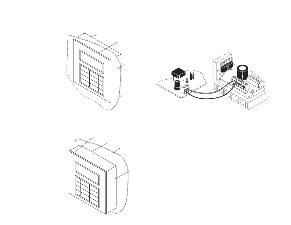
Flush Mounting
When you remove the MMI from the shipping carton, you will notice that it has two
parts. The first is a fairly thin section that contains the keypad, display and some
circuit boards. The other part is thicker and contains the telephone jack and a cable
that connects to the thin part.
When you flush mount the MMI in a
panel, only the thin section will stick
out from your panel - the large
portion mounts behind your panel.
You'll need to cut a precise section
from your panel. There is a
cardboard template in your box for
this purpose.
If you want the MMI to be dust proof and
watertight, you must place the black rubber
gasket between the thin part of the MMI and
your panel. Assemble the two halves using the
eight small screws.
Surface Mounting
An easier way to mount the MMI is to bolt the two halves together ahead of time,
using the eight small screws. If you want the MMI to be dust proof and watertight,
put the black rubber gasket between the two halves before screwing them together.
Then cut a hole in your panel for the cable
that runs between the MMI and the 7080i.
The hole must be at least 5/8" in
diameter for the connector to fit
through. You will also need two holes
that line up with the big mounting
holes in the MMI. The mechanical
outline on page 19 shows the location
of the big mounting holes.
When you mount the MMI to your
panel, you will need to use some kind
of sealant to keep dust and liquid out.
Silicone or latex caulking is okay, or you
can make your own gasket from a sheet of
compliant material like rubber or RTV.
-16-
-5-
1
2
3
➝
➝
4
5
6
➝
➝
7
8
9
YES
NO
.
0
SPACE
BKSP
ENTER
panel
sealant (not included)
MMI
gasket
(included)
1
2
3
➝
➝
4
5
6
➝
➝
7
8
9
YES
NO
.
0
SPACE
BKS
P ENTER
panel
MMI
(front section
and gasket)
MMI
(rear section)
Connecting the Power Supply
7080 Drive
DC Power Supply
If you need information about choosing a power supply, please read Choosing a
Power Supply below.
Connect the motor power supply + terminal to the driver terminal labeled "+V".
Connect power supply – to the drive terminal labeled "V–." Use 18 gauge wire. Be
careful not to reverse the wires.
Choosing a Power Supply
We recommend using an Applied Motion Products power supply with this drive.
Two models are available: the PS430 (30 volts DC at 4 amps) and the PS1050 (50
volts DC at 10 amps). The PS430 can also provide 500 mA of well regulated 5 volt
power for your logic circuits. If you do not choose an A.M.P. supply, please follow
the recommendations below.
Voltage
Chopper drives like the 7080i work by switching the voltage to the motor terminals
on and off while monitoring current to achieve a precise level of phase current. To
do this efficiently and silently, you’ll want to have a power supply with a voltage
rating at least five times that of the motor. Depending on how fast you want to run
the motor, you may need even more voltage than that. If you choose an
unregulated power supply, do not exceed 57 volts. This is because unregulated
supplies are rated at full load current. At lesser loads, like when the motor’s not
moving, the actual voltage can be up to 1.4 times the rated voltage. For smooth,
quiet operation, a lower voltage is better.