Wiring inputs, Connecting a proximity sensor to an input, Jogging – Applied Motion 7080i User Manual
Page 9: 7080i
-9-
-12-
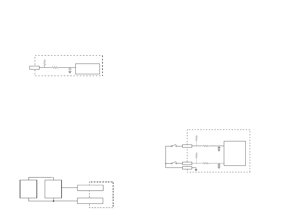
Wiring Inputs
Each input has a pull up resistor to the internal 5 volt power supply and an RC filter.
Because of the pull up resistor, if nothing is connected to an input, it defaults to the
"high" state. One way to control an input is by connecting a switch between the
input and ground. When the switch is closed, the input state is "low." When the
switch is open, it's "high." You can connect a relay the same way.
You can also connect an active signal to an 7080i input, as long as it's from a 0 - 5
VDC, or "TTL compatible" circuit. Open collector circuits are okay, too.
Connecting a Proximity Sensor to an Input
The best type of proximity switch to use is "NPN normally open." You will need an
external power supply to operate the sensor. Connect the power supply and
proximity switch terminals as shown in the diagram.
You may be concerned about wiring a proximity sensor to a 5 volt input when the
sensor is powered by 12 or 24 volts. Fear not: even though the sensor is powered
by a higher voltage, NPN type proximity sensors do not apply any voltage to the
output. They either switch the output terminal to ground, or leave it open circuit.
This is referred to as an "open collector" output. Thus, the 7080i input never sees
more than 5 volts.
If you are uncertain about the output voltage of your sensor, hook it up to your
power supply, but not the 7080i. Measure the voltage with a DC voltmeter at the
output terminal in both sensor states and make sure it does not exceed 5 volts. If
the sensor is truly open collector, the voltage will measure 0 in both states.
1K
100pF
10K
+5V
INPUT
7080i
Controller Chip
inside 7080i
Schematic Diagram of Inputs 1 - 4, cw jog and ccw jog)
7080i
GND
+
DC
Power
Supply
–
Proximity
Sensor
IN
output
+
–
The maximum voltage that can be applied to an input terminal is 5
volts DC. Never apply AC voltage to an input terminal.
Jogging
Two of the 7080i input terminals are provided for jogging the motor. The inputs are
labeled "JOG CW" and "JOG CCW". Connecting one of the inputs to ground
commands the drive to move the motor at a pre-designated speed until the contact
is opened. A relay or mechanical switch can be used to activate the jog inputs. 5
volt circuitry can also be used. The schematic diagram of the input circuit is shown
below.
If you're using a switch or relay, wire one end to the JOG input and the other to one
of the GND inputs. For active circuitry, connect the signal to JOG and the circuit
ground to GND.
If the 7080i is connected to a PC with the programming software running, the jog
inputs will function under two conditions:
1) if the program is not executing
2) if the program is executing a Wait Input command.
If the 7080i is operating in stand alone mode (i.e. without a computer attached) then
the jog inputs work when the program is executing the Wait Input instruction.
To set the Jog Speed and Jog Accel/decel rate, adjust the scroll bars in the main
programming window.
1K
100pF
10K
+5V
JOG CW
1K
100pF
10K
+5V
JOG CCW
GND
7080i
Controller Chip
inside 7080i