Selecting between full and half step, Using the tach output, Connecting logic – Applied Motion PDO2035 User Manual
Page 8
COM
DIR
Inside PDO 2035
2200
EN
2200
730
STEP
PDO2035
1000 Ohm
Resistor
1/4 watt
scope probe
Selecting Between Full and Half Step
-8-
-9-
STEP tells the driver when to move the motor one step. The drive steps on the
rising edge of the pulse. If the pulse is negative (low) the minimum width is 10
microseconds.
DIRECTION signals which way the motor should turn. See the step table on page 7
for details. The
DIRECTION signal should be changed at least 50 microseconds
before a step pulse is sent. If you change the state of the direction input
and send a step pulse at the same instant the motor may take a step in
the wrong direction.
ENABLE allows the user to turn off the current to the motor by setting this signal to
logic 0. The logic circuitry continues to operate, so the drive "remembers" the step
position even when the amplifiers are disabled. However, the motor may move
slightly when the current is removed depending on the exact motor and load
characteristics. If you have no need to disable the amplifiers, you don't
need to connect anything to the
ENABLE input.
Using the TACH Output
12345
1000
500
250
125
HALF
STEP
output
signal
5 usec
Locate the bank of DIP switches on the front panel. Switch
number 1 is labeled
HALF STEP. Sliding the switch
toward the
HALF STEP label sets the driver for that mode
of operation. The opposite position is full step. When set
to full step, the driver always uses "two phases on" mode
to provide maximum motor torque.
The PDO2035 has a pulse output to tell you how fast the oscillator is going. It
produces one pulse per motor step. You can connect this to a counter to provide
position information, or to a tachometer to provide speed data, or both. The pulse
output is optically isolated for noise immunity, which makes it more flexible and
more reliable, but also harder to hookup.
The TACH output is rated for 5 - 24VDC operation, up to 20 mA.
Connecting the Pulse Output
to a Frequency Counter
or Oscilloscope
Connecting the Pulse Output
to a PLC
TACH+
CW
CCW
TACH–
PDO2035
TACH+
TACH–
COMMON
INPUT
PLC
24 VDC
Power Supply
+
–
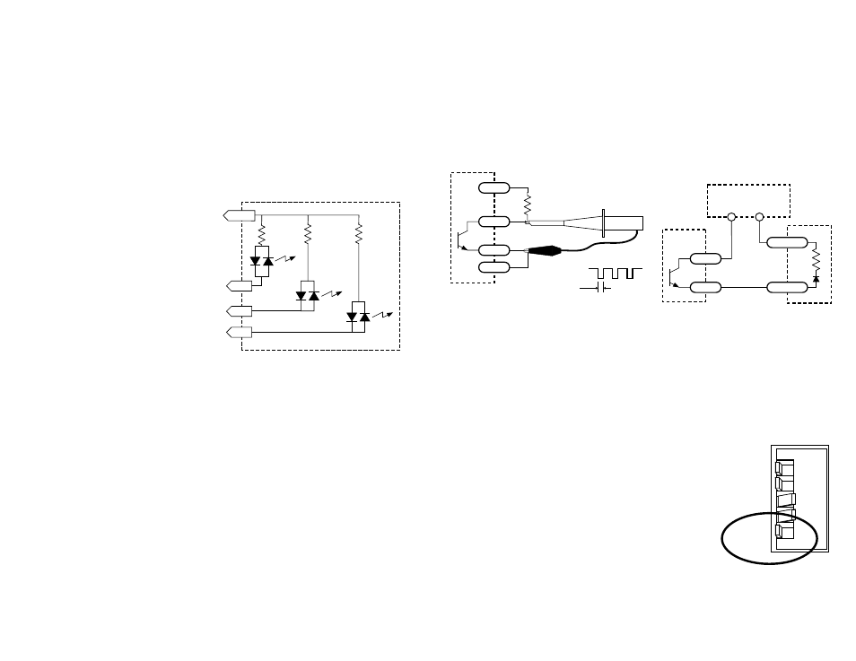
Connecting Logic
The PDO2035 drive contains optical isolation circuitry to prevent the electrical noise
(inherent in switching amplifiers) from interfering with your circuits. Optical
isolation is accomplished by powering the motor driver from a different supply than
your circuits. There is no electrical connection between the two: signal
communication is achieved by infrared light. When your circuit turns on or turns off
an infrared LED (built into the PDO2035) signals a logic state to the photo-
transistors that are wired to the brains of the drive.
A schematic diagram of the input circuit is shown on the right.
You must supply 5-24 volts DC to activate
the LEDs on the input side of the
optoisolators. The maximum current draw
is 30 mA.
If your controlling logic is 24V, it must be
capable of sinking at least 30 mA to control
each drive input. If you are using 5 volt
logic (TTL level) then each signal must sink
5 mA.
If your STEP, DIR and ENABLE signals are
sinking (NPN) then connect COM to your power supply +. If your signals are
sourcing (PNP) then connect COM to power supply -.