Limit switches, Jogging, Wiring a mechanical limit switch – Applied Motion Si3540 User Manual
Page 10: Wiring a limit sensor
-9-
Limit Switches
The Si3540 has two limit switch inputs, LIMIT CW and LIMIT CCW. By connect-
ing switches or sensors that are triggered by the motion of the motor or load, you
can force the Si3540 to operate within certain limits. This is useful if a program
error could cause damage to your system by traveling too far.
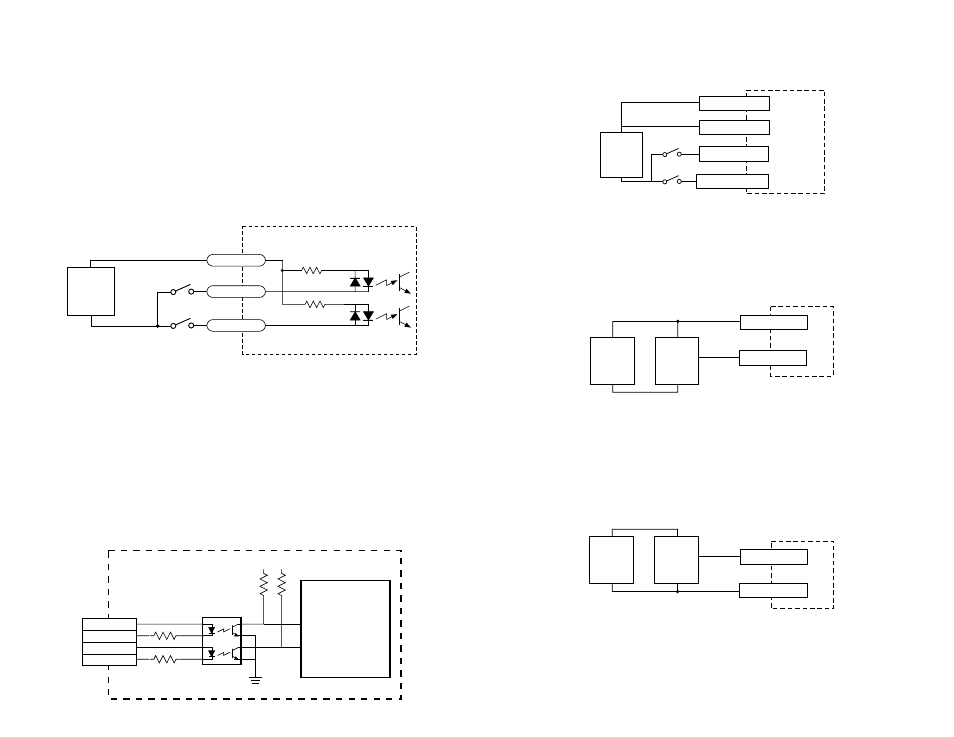
The limit inputs are optically isolated. This allows you to choose a voltage for your
limit circuits of 5 to 24 volts DC. This also allows you to have long wires on limit
sensors that may be far from the Si3540 with less risk of intoducing noise to the
Si3540. The schematic diagram of the limit switch input circuit is shown below.
2200
2200
inside Si3540
COM
CWJOG
CCWJOG
+
5-24
VDC
SUPPLY
-
Si3540
Controller
Chip
2200
10K
+5V +5V
3
4
1
2
CW LIMIT+
CW LIMIT–
CCW LIMIT+
CCW LIMIT–
TLP621 or
NEC PS2501
inside Si3540
Jogging
Two of the Si3540 input terminals are provided for jogging the motor. The inputs
are labeled “JOG CW” and “JOG CCW”. Activating one of the inputs commands the
drive to move the motor at a pre-designated speed until the contact is opened. A
relay or mechanical switch can be used to activate the jog inputs. 5-24 volt cir-
cuitry can be used. The schematic diagram of the input circuit is shown below.
If you’re using a switch or relay, wire one end to the JOG input and the other to the
power supply negative (-) terminal. Then connect the COM input to the power
supply positive (+) terminals.
-10-
If the sensor output goes low at the limit, select the option “closed”. If the output
is open, or high voltage, choose “open”.
Other sensors have sourcing outputs. That means that current can flow out of the
sensor output, but not into it. In that case, wire the sensor this way:
If the sensor output goes high at the limit, choose the program option “closed”. if
the output is low at the limit, select “open”.
Si3540
CCW LIMIT+
CCW LIMIT-
CW LIMIT-
+
5-24
VDC
SUPPLY
-
CW LIMIT+
Si3540
CW LIMIT-
+
DC
Power
Supply
–
Limit
Sensor
CW LIMIT+
output
+
–
Si3540
LIMIT-
+
DC
Power
Supply
–
Proximity
Sensor
LIMIT+
output
+
–
Wiring a Mechanical Limit Switch
You can use normally open or normally closed limit switches. Either way, wire
them as shown here.
Wiring a Limit Sensor
Some systems use active limit sensors that produce a voltage output rather than a
switch or relay closure. These devices must be wired differently than switches.
If your sensor has an open collector output or a sinking output, wire it like this:
Wiring for Sinking or Open Collector Output
Wiring for Sourcing Output