CIRCUTOR SYNCHROMAX Series User Manual
Synchromax, Increase speed decrease speed, Vgen vbb fr.gen fr.bb v% fr.% too fast too slow
Manual de Usuario
User´s Manual
PN: 430056003 REV A
PN: 430056003 REV A
M981899501-01-04A
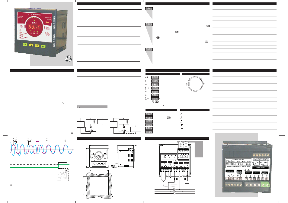
SynchroMax
SynchroMax
Visualización e Indicaciones / Display and Indications
Modos de Operación / Operation modes
Notas / Notes
Notas / Notes
Medidas / Measures
Mensajes / Messages
Simulación / Simulation
Condiciones de sincronización / Sychronization Conditions
92.0
96.0
96.0
81.5
5.3
+0,8
Agujero de panel
Panel cut-out
Holding piece
Brida de sujección
92.0
+0,8
Dimensiones: 96 x 96 x 81,5
Peso:
350 gr.
Material caja: ABS autoextinguible
Color caja:
Gris Antracita
Frontal:
IP54 (IP65 opcional)
Dimensions: 96 x 96 x 81.5
Weight:
510 gr.
Case material:Self-exting ABS
Case colour: Anthracite grey
Frontal:
IP54 (IP65 optional)
Dimensiones y datos mecánicos / Dimensions & Mechanical Data
SYNC
V
Increase
speed
Decrease
speed
SynchroMax
Enb
F
VGEN
VBB
Fr.GEN
Fr.BB
V%
Fr.%
TOO
FAST
TOO
SLOW
TOO
FAST
TOO
SLOW
V
V
V
Tbrk
V
F
F
F
F
ok
ok
ok
ok
ok
ok
ok
ok
j = 0
O
Breaker
Synchronism Relay
On
Tbrk es el tiempo que el contactor necesita para cerrar sus contactos
El SynchroMax compensa este tiempo, adelantando la orden de Sync
Tbrk is the time that the breaker needs to close its contacts
The SynchroMax compensates this time, advancing the Sync order
Off
Busbar
Generator
En un proceso de sincronización es necesario controlar las diferencias de
,
y
de las señales a sincronizar. Sólo cuando se
cumplan todas las condiciones, estaremos en condiciones de conectarlas.
Para ello, el nuevo
mide y calcula la diferencia de tensión en %, la
diferencia de frecuencia en % y el ángulo de fase. Asimismo tiene en cuenta el
retardo de conexión del contactor, dando la señal de sincronismo adelantada
para compensar éste.
Además el SynchroMax supervisa la df/dt (
,
),
y si ésta es muy grande no dará señal de sincronismo.
tensión frecuencia
fase
SynchroMax
ROCOF R
O C
O F
ate
f
hange
f requency
Función Bus Muerto. Si se habilita esta función, cuando la tensión principal esté por
debajo del valor de bus muerto y la frecuencia del grupo sea correcta (ésta será
ajustada por los relés de regulacion de velocidad) se producirá un pulso de
sincronismo. Para que el SynchroMax vuelva al estado de operación deberá
abrirse/cerrarse la habilitación externa (terminales 5 y 6) Ver Nota 1
In a synchronization process we need to control the
,
and
differences between the two signals to sinchronize. Only when all the conditions will be
reached, we will be in connection condition.
In order to control the above parameters , the new
measure and calculate
the voltage difference in %, the frequency difference in % and the phase angle.
In order to determine the exactly phase accordance, the SynchroMax calculates a
phase angle advance determined by the breaker closing time.
In addition, the SynchroMax supervise the
(
) and
if this value is too big no synchronization pulse will be allowed.
. If this option is enabled, when the busbar voltage is lower than the
Deadbus voltage and the generator frequency is correct (speed pulses are given in
order to reach it) one synchronization pulse is generated. To recover the normal
operation mode open/close the external control (5 and 6 terminal) To see Note 1
voltage frequency
phase
SynchroMax
R
O C
O F
ROCOF
Dead Bus Facility
ate
f
hange
f
requency
Nota1 / Note 1
El uso de Bus Muerto, requiere que se tomen medidas especiales, para asegurar que la
Red queda desconectada cuando se active la conexión del Generador, de no hacerse
asi, un retorno de Red significaría una entrada no controlada con desastrosas
consecuencias.
To use DeadBus facility require that special security measures will be considered, in
order to assure that the busbar is disconnected when the Generator is connected, if not,
return of busbar will be a non controlled input with disastrous results.
Tensión RMS
Frecuencia
Fase
Tiempo Contactor
R.O.C.O.F.
Bus Muerto
Voltage RMS
Frequency
Phase
Breaker time
R.O.C.O.F.
DeadBus
!
!
!
Rele de Syncronismo activado
Synchronism relay actived
Modo Asistido, pulsar
Assisted Mode, push
R.O.C.O.F. demasiado alto
R.O.C.O.F. too high
Función Bus Muerto ejecutada
Executed Deadbus function
Generador muy rápido (Fg > Fbb+3Hz)
Too fast generator (Fg > Fbb+3Hz)
Generador muy lento (Fg < Fbb-3Hz)
Too fast generator (Fg > Fbb+3Hz)
Símbolos / Symboles
SYNC
V
Enb
F
Control externo habilitado
External control Enabled
Diferencia de tensión dentro de márgenes
Voltage difference into margins
Diferencia de frecuencia dentro de márgenes
Frequency difference into margins
Acelera motor (terminales 16 y 18)
Increase speed (16 and 18 terminals)
Decelera motor (terminales 13 y 15)
Decrease speed (13 and 15 terminals)
Rele sincronismo (terminales 1 y 2)
Synchronism relay (1 and 2 terminals)
V
BB
V
GEN
Fr
.BB
Fr
.GEN
V
%
Fr.
%
Ángulo de desfase red-generador
Busbar-generator phase angle
Tensión principal
Busbar voltage
Tensión generador
Generator voltage
Diferencia tensión
Voltage difference
Diferencia frecuencia
Frequency difference
Frecuencia principal
Busbar frequency
Frecuencia generador
Generator frequency
V =
Vgen - Vbb
Vbb
x 100 (%)
Fr =
Fgen - Fbb
Fbb
x 100 (%)
Fg>Fbb
Fg<Fbb
Si la frecuencia del generador es superior a la
principal (TOO FAST, demasiado rápido), la
simulación analógica girará en sentido de las
agujas del reloj y viceversa.
If the generator frequency is higher than the
busbar (TOO FAST), the analogue simulation
turns clock-wise and vice versa.
Manual.En este modo el SynchroMax regulará la velocidad del motor,
dará todas las indicaciones pero nunca conectará el rele de
sincronismo. Este último deberá activarse manualmente.
Manually. In this mode the SynchroMax will control the motor
speed,will display all the measures and indications but never will
connect the synchronism relay. This should be connected manually.
Asistido. En este modo el SynchroMax regulará la velocidad del motor,
dará todas las indicaciones y si el usuario mantiene pulsada la tecla
el relé de sincronismo será activado en el momento oportuno, es decir,
para que éste se active deben haber condiciones de sincronismo y
debe estar pulsada la tecla
.
Assisted. In this mode the SynchroMax will control the motor speed,
display all the measures and indications and if the user mantain pushed
the
key the synchronism relay will be connected in the convenient
time, in other words, for connect the synchronism relay two conditions
should be done, to fulfil synchronism conditions and to having the
key pushed.
Automático. En este modo el SynchroMax regulará la velocidad del
motor, dará todas las indicaciones y el rele de sincronismo será
activado en el momento oportuno, es decir, todo el proceso se realizará
de forma automática.
Automatic. In this mode the SynchroMax will control the motor speed,
display all the measures and indications and the synchronism relay will
be connected in the convenient time, in other words, all the process will
be done automatically.
Características Técnicas /
1 de 2 /
Technical Data
1 of 2
Características Técnicas /
de 2 /
Technical Data
2
2 of 2
Tensión Alterna
Tensión Continua
Valores standard
Tolerancia
Margen de frecuencia
Consumo Máximo
Tensión Nominal
Frecuencia
Sobrecarga Permanente
Consumo
Tensión (R.M.S)
Frecuencia
Ángulo de fase
Display
Color
Ciclo de Presentación
Leds Auxiliares
Temperatura Almacenamiento
Temperatura de Uso
Tipo
Capacidad contacto (carga resis)
Max tensión conmutable
Max corriente conmutable
Max potencia conmutable
Esperanza de vida mecánica
Esperanza de vida eléctrica
Resistencia de aislamiento
Resistencia dieléctrica bob-cont.
Resistencia dieléctrica cont abrts
Resistencia choque funcional
Resistencia choque destructiva
Resistencia a la Vibración NO
Construcción
Valores standard
Consumo Máximo
Resistencia a la Vibración NC
110, 230, 400, 480V
-10/+15%
35...450Hz
10VA
9-18, 18-36, 37-72V
11VA
400V F-N, 565 F-F
35...80Hz
800V
< 500uA
Cl 1 +/-2dig
+/- 0.01Hz
+/- 0.5º
4 digits
Red, High Efficiency
2 x seg
30
-40...+70ºC
-10...+65ºC
contacto conmutado
8A 250Vac / 5A 30Vdc
250Vac / 30Vdc
8Aac / 5Adc
2,000VA / 150W
10,000,000 min
100,000 min
1,000M 500Vdc
4,000Vac
1,000Vac
100m/s
1,000m/s
10 to 55Hz, 1.5mm dob amp
10 to 55Hz, 0.8mm dob amp
Sellado /
2 x sec
change over contact
Sealed
W
2
2
Alternate current
Direc current
Standard values
Tolerance
Frequency band
Maximum Consumption
Nominal Voltage
Frequency band
Continuous Overload
Consumption
Voltage (R.M.S.)
Frequency
Phase angler
Display
Colour
Display rate
AuxiliaryLeds
Storage Temperature
Operation Temperature
Type
Contact rating (res. load)
Max switching voltage
Max switching current
Max switching power
Mechanical life expectancy
Electrical life expectancy
Isolation resistance
Dielectric strength coil-contacts
Dielectric strength open-contacts
Functional shock resistance
Destructive shock resistance
Vibration resistance NO
Construction
Standard values
Maximum Consumption
Vibration resistance NC
Alimentación Auxiliar / Auxiliary Supply
Circuitos de Medida / Measuring Circuits
Precisión / Accuracy
Display
Condiciones Ambientales / Environmental conditions
Reles / Relays
Normas de Diseño / Design Standards
IEC 1010, IEC 348, IEC 664, IEC 801, EN 50081-2, EN 50082-2
Las cargas inductivas reducen fuertemente la esperanza de vida de los relés. Si los reles
deben controlar motores de continua, es muy adecuado intercalar reles auxiliares externos, y
en las bobinas de estos montar supresores de transitorios.
Inductive loads reduce very much the relays life expectancy. If the relays should control dc pilot
motors, is very recommended to use external auxiliary relays with transient suppressor in his coil.
SUPPRESSOR
DEVICE
SYNCHROMAX
DC
POWER
SOURCE
AUX.RELAY
COIL
AUX.RELAY
COIL
SUPPRESSOR
DEVICE
SYNCHROMAX
DC
POWER
SOURCE
Supresor en bobina
Coil suppressor
Supresor en contact
Switch suppressor
Nota Importante / Important Notice:
!
EC (Control externo): La conexión abierta desabilita el relé de sincronismo (breaker)
EC (External control): The connection opened disables the synchronism relay (breaker)
*
NC
ENABLED
NC
NC
NO
NO
NO
L1
L1
L2
L2
INCREASE
DECREASE
SPEED CONTROL
SYNCHRO
Ext Ctrl
BusBar
Gen
AUX
SUPPLY
+
_
AUXILIARY SUPPLY
BusBar & Gen Range: 20...600V 30...80Hz
110
400
480
230
9...18
18...36
36...72
AC(V)
30...80Hz
DC(V)
1
2
3
4
5
6
7
8
10
11
12
13
18 17 16 15 14
9
Aux.
Supply
B
R
E
A
K
E
R
L1
Busbar
Generator
L1
L2
L2
L3
L3
EC
*
S
P
E
E
D
C
O
N
T
R
O
L
C
O
N
T
R
O
L
V
E
L
O
C
I
D
A
D
Diagramas de Conexión / Wiring Diagrams