Mixed ground stack – d&b Z5396 Y Base plate User Manual
Page 7
3. At the rear release both Locking pins of the upper cabinet's
Splay link.
4. Fold the Splay link of the upper cabinet into the rigging strand
of the bottom cabinet.
5. Raise the upper cabinet until the hook of the Splay link hooks
into the preset Locking pin.
6. Hold the cabinet in place and insert the second Locking pin
(Safety pin) from the bottom cabinet to fix the Splay link in
place.
To add further cabinets, proceed in the same manner until the
assembly is completed.
6. Rig the cabling
Connect the cables and link cables according to the number of
amplifier channels and cabinets used.
7. Check the assembly
Recheck the actual status of the entire assembly.
–
Check all Front links on both sides of the cabinets and ensure
all Locking pins are properly inserted and locked.
–
Check the splay angle settings and the Splay links on the rear
of the cabinets and ensure all Locking pins are properly
inserted and locked.
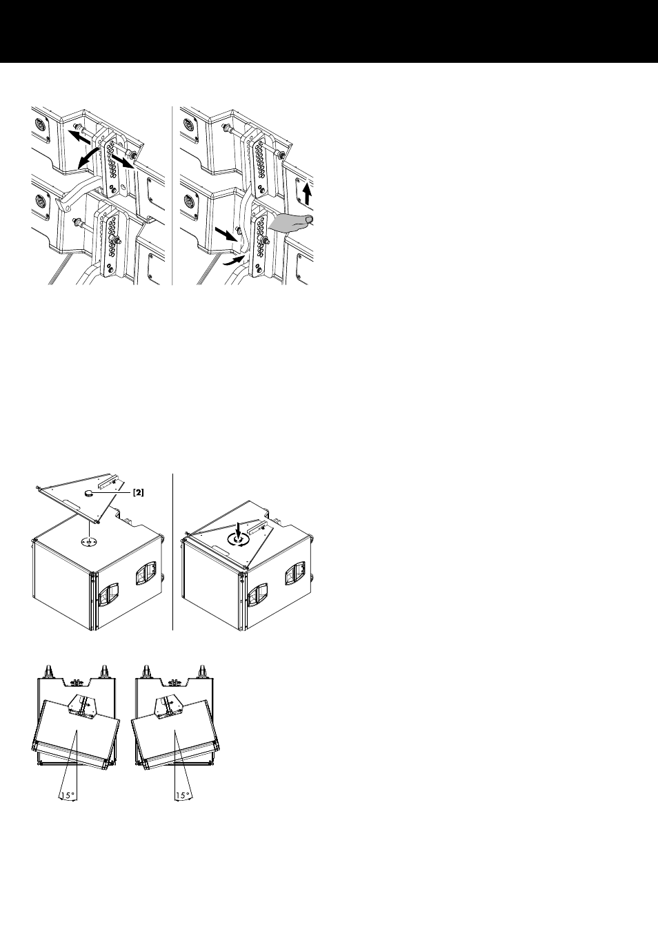
2.2.2. Mixed ground stack
For this purpose, the Base plate is equipped with an M20 hand
bolt
[2] which can be attached to the M20 threaded insert of the
respective subwoofer.
Þ Simply fit the Base plate onto the M20 threaded insert of the
subwoofer and tighten the hand bolt.
The assembly of the Y8/Y12 cabinets on top of the subwoofer is
carried out in the same manner as described in the previous
chapter.
Horizontal alignment
In addition, the Y8/Y12 assembly on top of the Subwoofer can be
horizontally aligned to the left or to the right. However, due to the
rubber feet of the Base plate, the angle is limited to 15° since the
front rubber feet should always rest on the top panel of the
subwoofer.
Þ To perform the alignment, slightly slacken the hand bolt, align
the assembly and retighten the hand bolt.
d&b Z5396 Rigging manual 1.1 en
7