Mounting options and angle settings – d&b Z5398 YP Horizontal bracket User Manual
Page 5
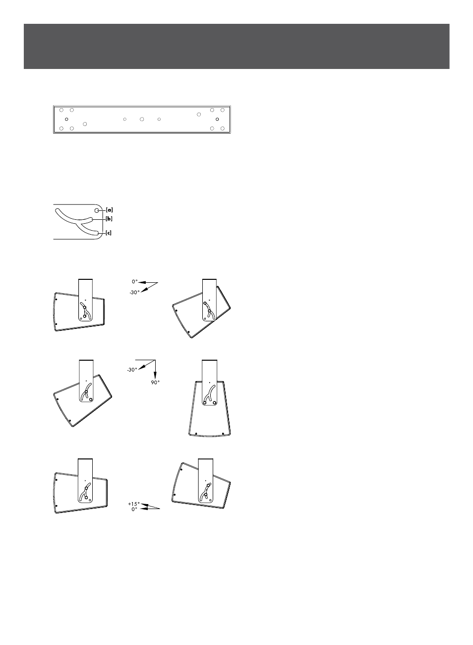
1.4. Mounting options and angle settings
Mounting holes are provided on the tie bar of the bracket.
One centered 9 mm (0.35") hole is provided at each end of the tie
bar for fixing the bracket directly to walls or ceilings or other
suitable surfaces.
Two centered 9 mm (0.35") holes at the d&b standard spacing of
115 mm (4.5") are provided to allow the attachment of the Z5010
TV spigot.
Five mounting holes are provided at each end of the tie bar to
attach the Z5044 MAX Bracket connector, the Z5053 Ci60/Ci90
Bracket connector or the Z5054 Ci60/Ci90 Flying adapter.
One 11 mm (0.43“) hole
[a] and two semi-circular slots [b], [c]
are located at each end of the bracket.
Using the M10 threaded inserts at the top and bottom of the
loudspeaker cabinet, the bracket can be attached in two directions
to allow angle settings over a range of 105°, starting from +15°
through to –90°. The following mounting options and angles
settings are possible.
Option 1
The bracket is attached to the cabinet with hole
[a] facing to the
front of the cabinet. Both bolts are fitted into slot
[b].
The vertical coverage angle can be set over a range of 30°,
starting from 0° to –30°.
Option 2
The bracket is attached to the cabinet with hole
[a] facing to the
back of the cabinet. One bolt is fitted into hole
[a] and the second
one is fitted into the axis of slot
[b] and slot [c] to allow the bolt to
move in slot
[c].
The vertical coverage angle can be set over a range of 60°,
starting from –30° to –90°.
Option 3
The bracket is attached to the cabinet with hole
[a] facing to the
back of the cabinet. Both bolts are fitted into slot
[b].
The vertical coverage angle can be set over a range of 15°,
starting from 0° to +15°.
Z5398 Mounting holes
d&b Z5398 Mounting instructions 1.1 en
5