Front & rear panels – Holland Electronics HMA-860H User Manual
Page 4
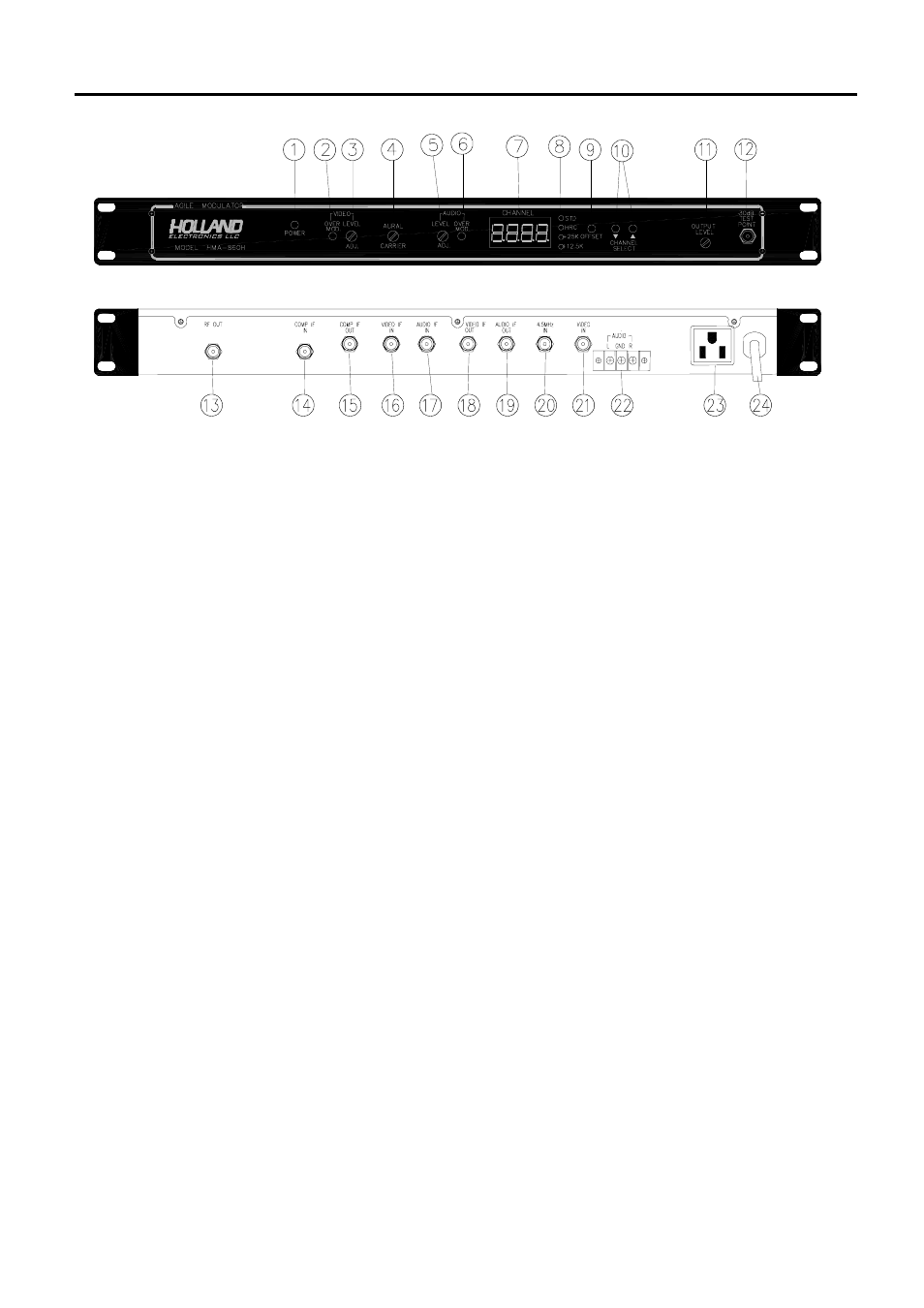
Front & Rear Panels
1. Power On LED:
Indicates power is on when lit.
2. Video modulation LED :
Indicates video over-modulation when lit.
3. Video Modulation Adjust :
Used to set video modulation level.
4. Video/Audio Ratio adjustment :
Used to set level of audio carrier.
5. Audio Modulation Adjust :
Used to set audio modulation level (volume).
6. Audio Modulation LED :
Indicates aural over-modulation level when lit.
7. Channel Display :
Indicates which channel is active.
8. Offset Indicator LED’s :
Indicates if standard or off-set formats are active.
9. Offset selector :
Used to select standard or off-set formats.
10. Channel selectors :
Used to select desired channel.
11. RF Level Adjust :
Used to set RF level.
12. -30 dB Test Point :
Used to monitor RF output level.
13. RF Output port :
Connect this port to distribution system.
14. Composite I.F. Input :
Input from I.F. scrambler or I.F. output.
15. Composite I.F. Output :
To I.F. input or to scrambling device.
16. Video I.F. Input (45.75 MHz) :
Video carrier I.F. input from video scrambling
device or video carrier I.F output.
17. Audio I.F. Input (41.25 MHz) :
Sound carrier I.F. input from audio scrambling
device or sound carrier I.F. output.
18. Video I.F. Output (45.75 MHz) :
Video carrier I.F. output to scrambling device or
video carrier I.F. input.
19. Audio I.F. Output (41.25 MHz) :
Sound carrier I.F. to audio scrambling device or
sound carrier I.F. input.
20. 4.5 MHz Input :
Input for BTSC stereo encoder operation.
21. Video Input :
Accepts any baseband video output source such
as a satellite receiver, VCR, security camera or
cable converter.
22. Audio Input (Left and Right) :
Accepts any baseband audio output source such
as a satellite receiver, VCR, security camera or
cable converter.
23. Convenience Outlet :
Standard U.S.A. type shown
24. Power Cord :
Three wire, standard U.S.A. type.