The following table defines the response b format – Holland Electronics NE 1101L User Manual
Page 17
- 17 -
Forward Optical Receiver
Operation Manual
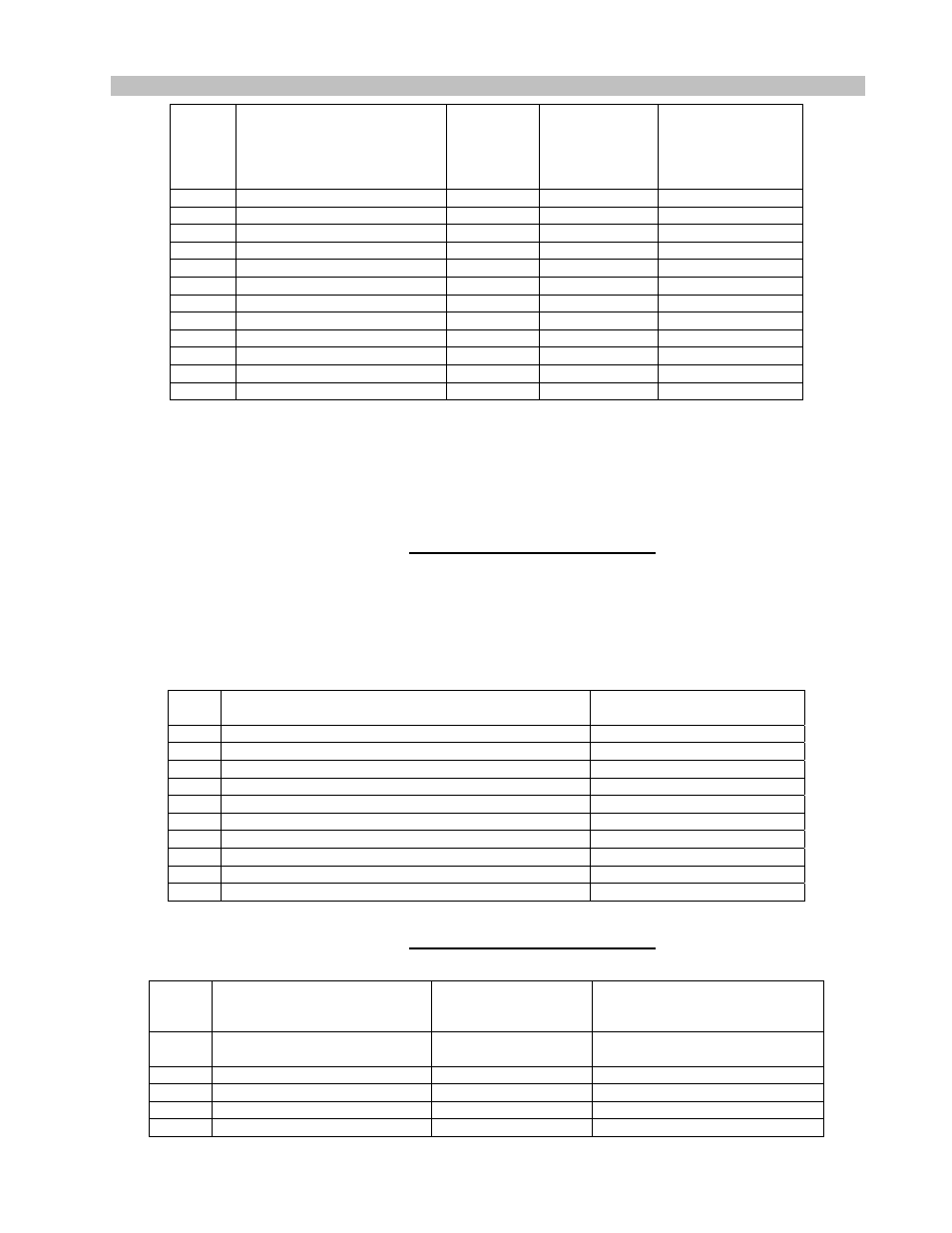
Line
#
Heading
(Column 1 – 16)
Alarm
Indicator
(note*)
(column
17-19)
Value
Display
Format
(column
20-30)
Unit
(column
31-33
1
OPT CHA
dd.d
mW and dBm
2
OPT CHB
dd.d
mW and dBm
3
RF LVL
+dd.d
dB
4
GAIN CTRL LVL
dd.d
V
5 12V
CURRENT
dd.d
A
6 24V
CURRENT
dd.d
A
7 24V
DC
dd.d
V
8 12V
DC
dd.d
V
9
5V DC
dd.d
V
10 ID
CODE
FFFF
11 FIRMWARE
VER
d.dd
12 <CR><LF><CR><LF>
Note1: In normal condition, the alarm indicator field should remain blank.
Any “A” in the field indicates the associated value is in alarm condition.
Note2: In shutdown mode, the data in line 1 through 9 are invalid.
And for a single pump model, all pump2 entries are skipped.
Note3: ID CODE display FFFF for Hexadecimal.
TABLE 2: Response to Command S
The following table defines all types of alarm message used in the response A. One line of alarm text
will be returned for each type of existing alarm(s) in the unit. Each line is ended with one set of
<Carriage Return> and <Line Feed>, and the whole message block is terminated with TWO set of
<CR><LF>.
Alarm
#
Alarm Text
(column 1-50)
Remark
1 NO
ALARM
2
CHA LOSS OF OPTICAL POWER
3
CHB LOSS OF OPTICAL POWER
4
LOSS OF RF SIGNAL
5 LOSS
OF
PILOT
TONE
6 24VDC
VOLTAGE
ALARM
7 12VDC
VOLTAGE
ALARM
8 5VDC
VOLTAGE
ALARM
9
24VDC CURRENT ALARM
10 12VDC
CURRENT
ALARM
TABLE 3: Response to Command A
The following table defines the response B format.
Byte
#
Content
Translation
formula
Remark
0 <C0>
Leading
marker
(C0 in hexadecimal)
1
OPT CHA
1 = 0.02 mW
Range: 0 – 255
2
OPT CHB
1 = 0.02 mW
Range: 0 – 255
3
RF LVL
Scalar 1=0.1dB
Range: (nagtive99) to 99
4
GAIN CTRL LVL
128 = 10 V
Range: 0 – 255