Holland Electronics NE 1101L User Manual
Page 5
- 5 -
Forward Optical Receiver
Operation Manual
Indicator/Control Description
Power
Main power indicator
Green – AC Power On
OFF -- AC Power OFF
Ch A Loss
Ch A Optical Power
OFF – Optical input power > Channel A optical power low
threshold
RED Flashing – A port Optical input < Channel A optical power low
threshold
RF Loss
RF signal power less than RF power threshold.
Auto Gain Ctrl
Displays status of the gain control mode
GREEN – AGC mode
OFF – MGC mode
Com Status
Displays status of RS485 or RS232 connection
GREEN – Data transmit or received
Button Rest
Reset System, Note: it will restart all system.
Button UP
Scroll up
Button DN
Scroll up
Button ENT
Select highlighted item on LCD display
RF MONITOR
–20dB
F-type female connector, Monitoring output port signal, Measured
value is 20 dB below actual value. Accuracy to
±1 dB.
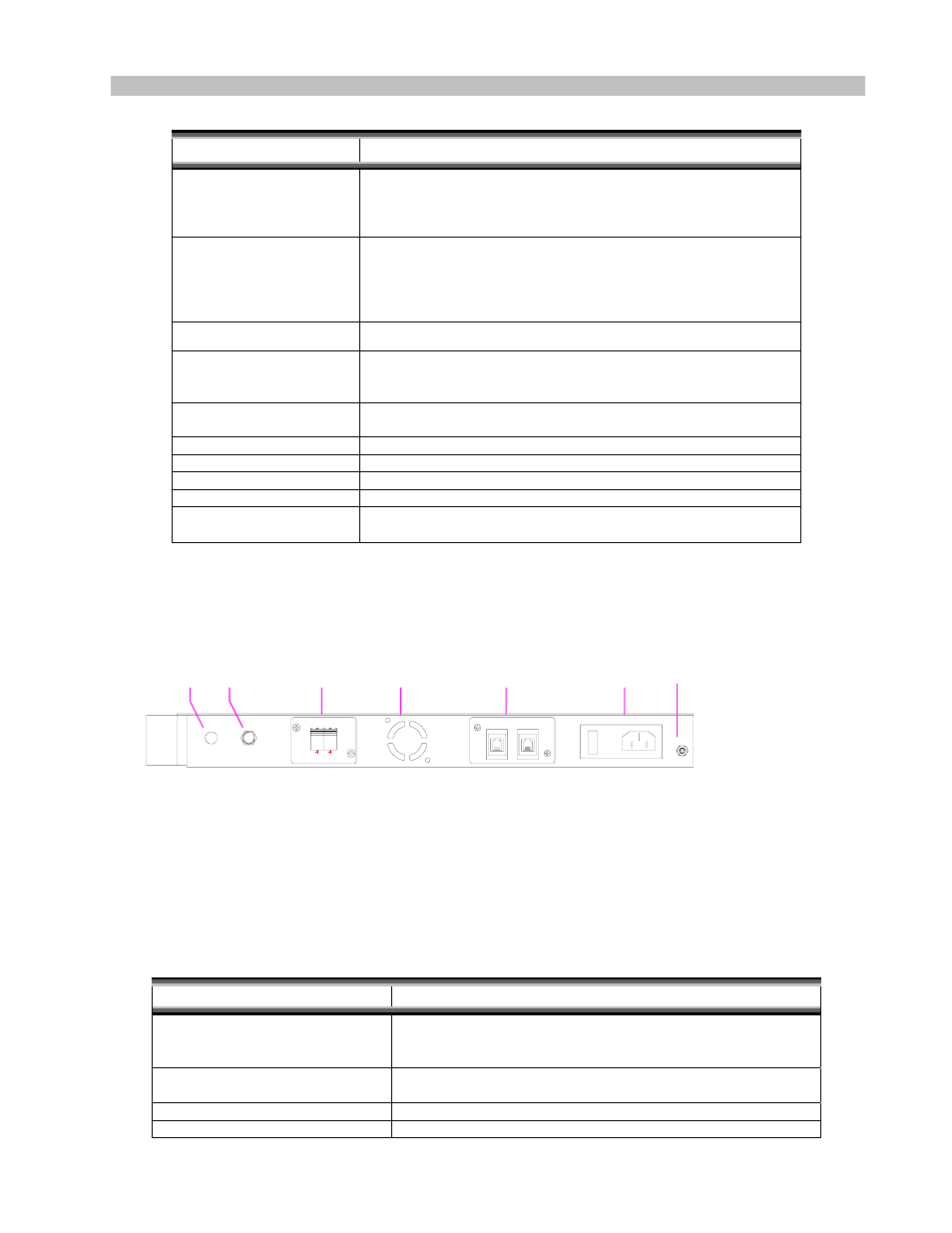
Rear Panel
B
A
RS-485
OFF
ON
OPTICAL
90V~220V 50/60Hz
FUSE 3.15A
Connector/Control Description
AC Power In(ON/OFF Switch,
Plug, Fuse)
AC power plug and main power switch. Fuse is rated 250V、
3.15A. For inspection or replacement, press down on the fuse
cap and turn to loosen.
RS-485 Interface
Provides connection to an external computer through RS-485 for
monitoring and configuration setup purposes
Dummy FAN Hole
Dummy: Not used in this type
A/B Port Optical Input
Optical Input connectors are SC/APC type. For connection, use
Dummy
Hole
RF
Output
A/B
Port
Optical
Dummy
FAN
Hole
RS485
Interfac
AC
Power In
Groundin
g spacer