Lωgic™ 4x36 product linking, Installation – ILUMINARC LΩGIC™ 4X36 User Manual
Page 11
Installation
LΩGIC™ 4X36 User Manual (Rev. 10)
7
Do not use the
splitter as a
coupler.
All cables must
be terminated to
a fixture.
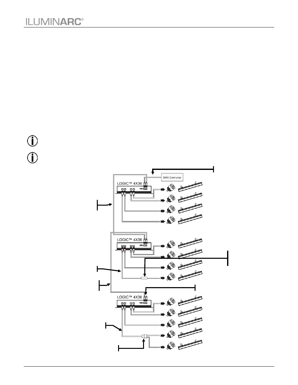
LΩGIC™ 4X36 Product Linking
The following steps provide the easiest method for connecting a set of one or more
LΩGIC™ 4X36 units to the same DMX cable.
1. Connect the RJ-45 plug of the DMX to RJ-45 adapter to the “DMX In” RJ-45 jack on
the first
LΩGIC™ 4X36 product.
2. Connect the XLR male connector of the DMX to RJ-45 adapter directly to the “DMX
Out” (female) connector on the DMX controller or to the DMX cable coming from the
DMX controller.
3. Connect one of the RJ-45 plugs of the signal patch cable to the “DMX Out” RJ-45 jack
on the first
LΩGIC™ 4X36 product.
4. Connect the other RJ-45 plug of the signal patch cable to the “DMX In” RJ-45 jack on
the second
LΩGIC™ 4X36 product.
5. Continue linking the
LΩGIC™ 4X36 products using more signal patch cables, as
shown in the diagram below.
ILUMINARC recommends using a signal terminator after the last
LΩGIC™ 4X36 product.
The easiest way to assemble a signal terminator is by soldering or crimping a 120 ohms
resistor between the terminals corresponding to DATA + and DATA – on a RJ-45 jack.
Another method consists in soldering the 120 ohms resistor to a short cable coming out of a
RJ-45 plug. Once assembled, connect the terminator to the “DMX Out” connector of the last
LΩGIC™ 4X36 product.
RJ-45 to DMX adapter
LED patch cable
Signal patch
cable
LED patch cable
RJ-45 coupler
(included with
controller)
Terminator or RJ-45 to DMX adapter
Signal patch
cable
Optional splitter