Ilumicon and dmx controllers, Ilumicode control panel description, Ilumicode connections – ILUMINARC Ilumipod™ 36g2 IP User Manual
Page 5: Ilumicode connection diagram
Ilumipod™ 36g2 IP QRG
EN
5
Ilumicon and
DMX
Controllers
To control/operate the Ilumipod™ 36g2 IP, use either an Ilumicon or a
DMX controller. Use the standard DMX connection as shown in the DMX
Junction Box Wiring section to connect this product to any standard DMX
controller.
Ilumicode
Control Panel
Description
Button
Function
<MENU>
Exits from the current menu or function
<ENTER>
Enables the currently displayed menu or sets the currently
selected value into the selected function
<UP>
Navigates upwards through the menu list and increases the
numeric value when in a function
<DOWN>
Navigates downwards through the menu list and decreases
the numeric value when in a function
Ilumicode
Connections
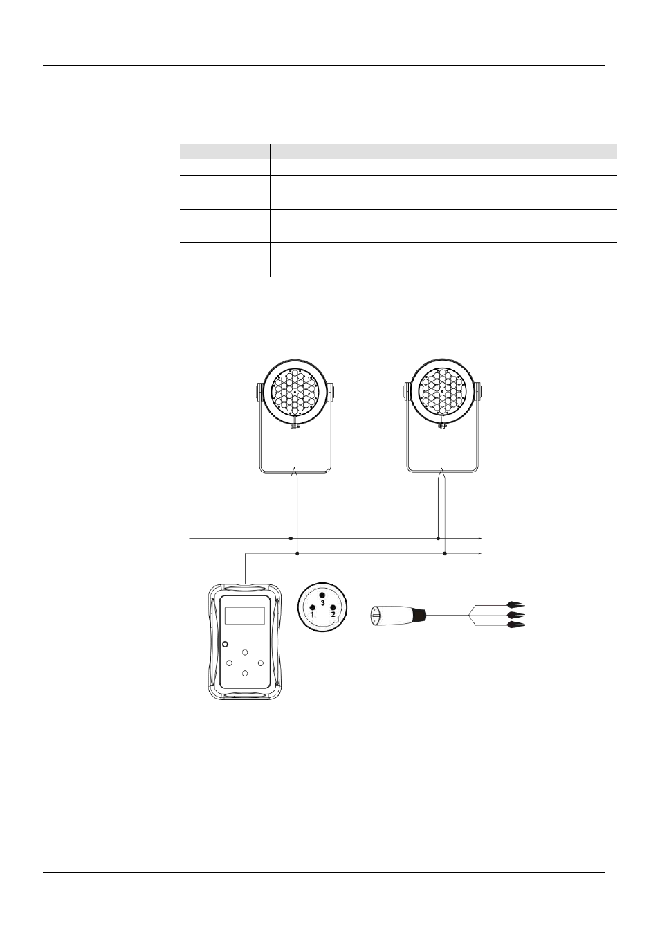
This diagram shows how to control multiple products at the same time. All
connected products will be assigned to the same DMX address.
To assign individual DMX addresses to each product, connect the
Ilumicode to each product individually. Be sure to disconnect the DMX
output of the product being configured if other products are connected to it.
Ilumicode
Connection
Diagram
ILUMINARC® suggests connecting no more than 20 products in this
mode, keeping the total distance to less than 60 m (197 ft). If not, you may
need to use an optically isolated signal amplifier.
1: Gnd
(Black Clip)
2: Data – (Green Clip)
3: Data + (Red Clip)
1: Gnd
2: Data –
3: Data +
Power
Signal
Ilumicode
Addresser
DMX Output
Signal Connector
To
Other
Products