Ac power, Power consumption, Junction box wiring – ILUMINARC Ilumipod™ Inground Tri-12 IP User Manual
Page 12: Power wiring, Installation
Installation
8
Ilumipod Inground Tri-12 IP Optic WW User Manual Rev. 3
Always connect
the Ilumipod
Inground Tri-12 IP
Optic WW to a protected
circuit with an appropriate
electrical ground to avoid
the risk of electrocution or
fire.
Never connect
the Ilumipod
Inground Tri-12
IP Optic WW to a rheostat
(variable resistor) or
dimmer circuit, even if the
rheostat or dimmer
channel serves only as a
0 to 100% switch.
Make sure to
connect the
Ilumipod
Inground Tri-12 IP Optic
WW to a power line with
the proper voltage and
frequency, as per the
specifications in this
manual or on the product’s
sticker.
AC Power
The Ilumipod Inground Tri-12 IP Optic WW has an auto-ranging power supply that works
with an input voltage range of 100~240 VAC, 50/60 Hz.
Make sure that you are connecting this product to the proper voltage, as per the specifications
in this User Manual or on the product’s sticker.
Power Consumption
To determine the power requirements for the Ilumipod Inground Tri-12 IP Optic WW, refer to
the label affixed to the side of the product. Alternatively, see the
The listed current rating indicates the maximum current draw during normal operation.
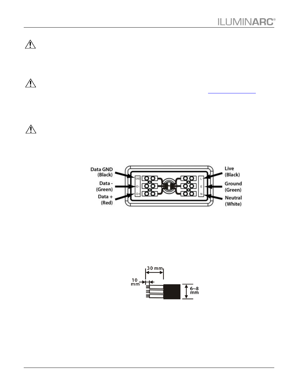
Junction Box Wiring
The Ilumipod Inground IP products have an IP67-rated junction box where the power and
signal cables come into the unit. The cables access the junction box through individual (signal
and power) IP67-rated stainless steel gland nuts.
Make sure that the junction seal is clean before placing the cover back on. In addition, tighten
the gland nuts and the junction cover to prevent water from entering the junction box and
causing a short.
The figure below shows the connections in the junction box.
Power Wiring
To provide AC power for any of the Ilumipod Inground IP products, you must run a single
SJTW rated 3-conductor cable (AWG18/3, 6~8 mm external diameter) from the power
distribution box into the installation sleeve and the product’s junction box.
Strip the end of the AC power cable that will connect to the junction box as indicated in the
figure.