Audio in-, outputs, Analogue inputs, Connecting speakers – KLING & FREITAG K&F TOPAS User Manual
Page 22
User's manual
System Amplifier K&F TOPAS
KLING & FREITAG GMBH © 2014
Version 3.1
Page 22 of 65
5.5
Audio Functions
5.5.1
Audio In-, Outputs
5.5.1.1
Analogue Inputs
Three symmetrical inputs (Channel 1, Channel 2, PRIO) are available to you. Channels 1
and 2 are designed as XLR connectors [illus. C, D] with a link connector and as a clamp
connector [illus. B]; the priority input is implemented as a clamp connector only [illus. A].
Input sensitivity and routing can be switched (see chapter Input Sensitivity on page [24]).
All analogue inputs of a channel are internally connected to one another in parallel.
5.5.1.2
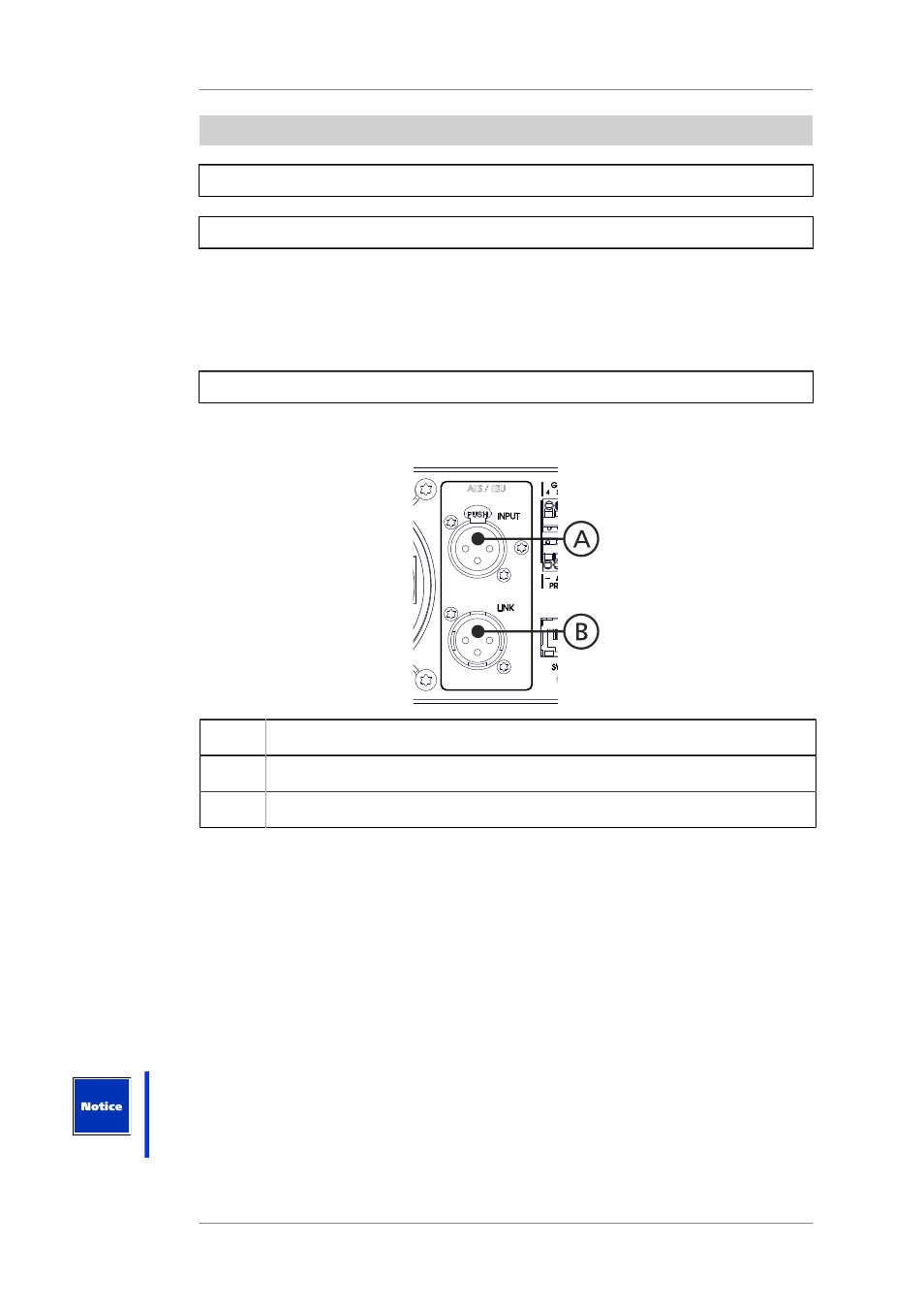
AES/EBU digital input (can be optionally activated)
In order to apply digital audio signals you can activate the AES/EBU interface with a
password. Please contact your dealer.
Position
Description
A
Input for digital audio signals, balanced AES/EBU compatible.
B
AES/EBU output, the signal is balanced and amplified internally.
The XLR connectors and the AES/EBU interfaces are always mounted.
In order to apply digital audio signals you can activate the AES/EBU interface with an
optionally available password. Please contact your dealer.
The interface supports the following data structures:
•
Sampling rate 44.1 - 96kHz
•
Word length 16, 18, 20 and 24bit
The signal can be looped through to another device via the link connector. The signal is
balanced and amplified internally.
In newer devices, there is a hardware bypass to ensure that a subsequent device is not
separated from a present signal in case there is no mains voltage.
Under ideal circumstances, the maximum possible cable length for AES/EBU signals is approx.
300 meters. Whether or not this cable length can actually be reached depends on the
auxiliary device and the quality of the cabling.
If there are problems with the transmission, it may be helpful to reduce the sampling rate.