Input sensitivity, Routing, Gain control – KLING & FREITAG K&F TOPAS User Manual
Page 24: Front panel gain control
User's manual
System Amplifier K&F TOPAS
KLING & FREITAG GMBH © 2014
Version 3.1
Page 24 of 65
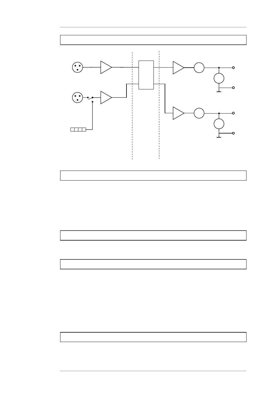
5.5.3
Input Signal Processing
CH 1
CH 2
P RIO
A
V
1+
1-
A
V
1+
1-
DS P
Output 1
Output 2
S e ns itivity
Ga in,
filte r,
routing
P owe ra mp
5.5.3.1
Input Sensitivity
The analogue inputs have a switchable gain to make optimal adjustments to the signal source
level. This also changes the overall gain that is specified in the web interface. You can adjust
the gain in the web interface in the menu item. (see page 31)
To minimise the total noise level of the system, you should always use the lowest possible
value at which no distortion occurs.
The function 'Auto Attenuation' enables an automatic gain switching when an overload
occurs.
5.5.3.2
Routing
You can assign any input channel (Input 1, Input 2) or the sum signal (Mono Mix) to each
amplifier channel. To avoid clipping, the sum signal is attenuated by 6dB.
5.5.3.3
Gain Control
The gain of a channel can be set by three input ways: By entering values in 'Group Gain' and
'Gain' and with the horizontal slider. (see page 31)
•
input sensitivity: Global for both channels (see page 24)
•
Gain setting of the channel: Gain in this DSP channel. The gain is individually
adjustable.
•
Only valid for the remote software, available at a later date: Gain of the group:
gain factor in this DSP channel, adjustable when assigning to a group. This value is
assigned when operating via GPI, remote software or XML for gain control of a group
of channels.
5.5.3.4
Front Panel Gain Control
You can adjust the volume of both channels with the two gain controls behind the left front
panel.