2 arrayed speaker systems (cluster), 1 horn not rotated – KLING & FREITAG K&F CA 1515-9 User Manual
Page 18
User's Manual
CA 1201, CA 1215-6 /-9, CA 1515-6 /-9
KLING & FREITAG GMBH ©1998 - 2015Version 4.0, 07.05.2015
Page 18 of 53
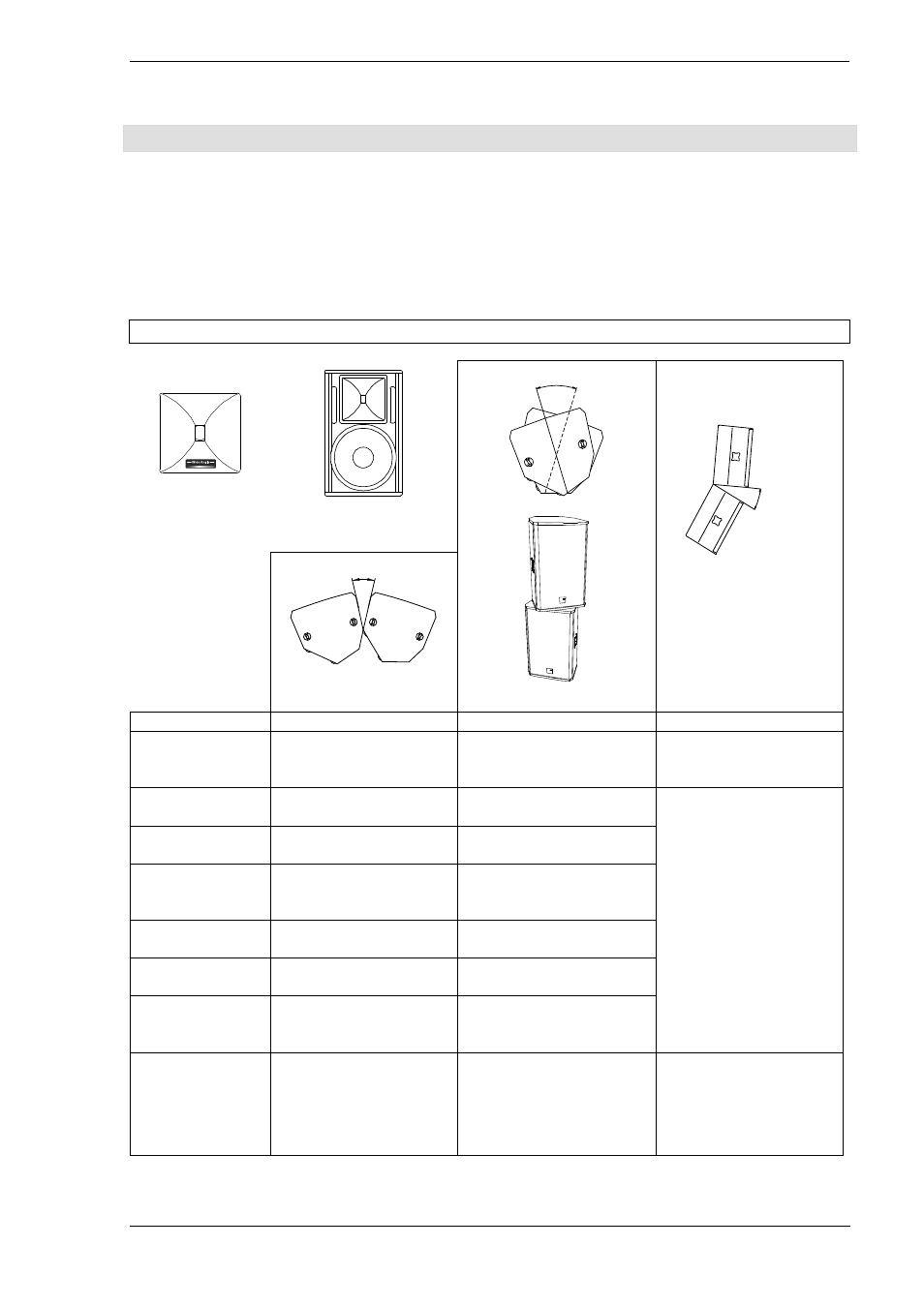
10.2 Arrayed Speaker Systems (Cluster)
If the loud
If the loud
If the loud
If the loudspeakers are operated through the optional K&F System Controller, we reco
speakers are operated through the optional K&F System Controller, we reco
speakers are operated through the optional K&F System Controller, we reco
speakers are operated through the optional K&F System Controller, we recom
m
m
mmend to turn
mend to turn
mend to turn
mend to turn
on the 'Top Low Cut' filter for clustered operation. Thus the fre
on the 'Top Low Cut' filter for clustered operation. Thus the fre
on the 'Top Low Cut' filter for clustered operation. Thus the fre
on the 'Top Low Cut' filter for clustered operation. Thus the frequency response for this application can
quency response for this application can
quency response for this application can
quency response for this application can
be optimised (see also user’s manual of the K&F System Co
be optimised (see also user’s manual of the K&F System Co
be optimised (see also user’s manual of the K&F System Co
be optimised (see also user’s manual of the K&F System Con
n
n
ntrol
trol
trol
troller).
ler).
ler).
ler).
When operating the systems without a K&F System Controller in a clustered con-figuration, the signal level of
frequencies below 300 Hz should be reduced by 3-4 dB.
10.2.1 Horn not rotated
*If several 90° systems are clustered, unwanted interference effects may appear. As a result, we do not gen-
erally recommend clustered configurations of CA 1201, CA 1215-9 and CA 1515-9 systems. If wide angles
are to be covered, we recommend the use of several 60° or 65° systems in one cluster.
Horn not
rotated
Standing
speaker
Winkel 2
between middle axes
Winkel 3
A smaller angle 3 results in
a smaller vertical coverage
angle but increases the
sound power level.
Winkel 1
between the sides of the
speakers
Combination
Combination
Combination
Combination
Angle 1
Angle 1
Angle 1
Angle 1
Angle 2
Angle 2
Angle 2
Angle 2
Angle 3
Angle 3
Angle 3
Angle 3
CA 1201 with
CA 1201
45°-55°
not generally recom-
mended*
55°-65°
not generally recom-
mended*
20°-35
CA 1215-6 with
CA 1215-6
30°
40°
20°-30°
CA 1215-6 with
CA 1215-9
35°
45°
CA 1215-9 with
CA 1215-9
40°-50°
not generally
recommended*
50°-60°
not generally
recommended*
CA 1515-6 with
CA 1515-6
30°
40°
CA 1515-6 with
CA 1515-9
35°
45°
CA 1515-9 with
CA 1515-9
40°-50°
not generally recom-
mended*
50°-60°
not generally recom-
mended*
Application
Increasing the horizontal
coverage angle, e.g. for
wide audience planes
Increasing the horizontal
coverage angle and sound
power level for larger dis-
tances
Increasing the vertical cov-
erage angle, e.g. for cover-
ing balconies or for in-
creased sound power level
for larger distances