Integrated peripherals, Onchip ide device – NEXCOM NISE 101 User Manual
Page 56
Copyright © 2010 NEXCOM International Co., Ltd. All Rights Reserved.
43
NISE 101 User Manual
Chapter 4: BIOS Setup
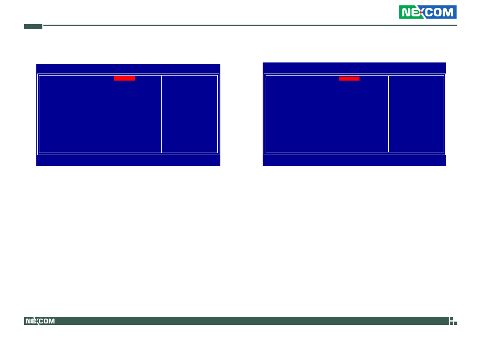
Integrated Peripherals
F7: Optimized Defaults
Phoenix - AwardBIOS CMOS Setup Utility
Integrated Peripherals
Item Help
Menu Level
↑↓→←
: Move
Enter: Select
F1: General Help
+/-/PU/PD: Value
F10: Save
ESC: Exit
F5: Previous Values
F6: Fail-Safe Defaults
F7: Optimized Defaults
OnChip IDE Device
Onboard Device
Super IO Device
USB Device Setting
Press Enter
Press Enter
Press Enter
Press Enter
OnChip IDE Device
IDE HDD Block Mode
IDE DMA Transfer Access
On-Chip Primary PCI IDE
IDE Primary Master PIO
IDE Primary Slave PIO
IDE Primary Master UDMA
IDE Primary Slave UDMA
On-Chip Secondary PCI IDE
IDE Secondary Master PIO
IDE Secondary Slave PIO
IDE Secondary Master UDMA
IDE Secondary Slave UDMA
*** On-Chip Serial ATA Setting ***
On-Chip Serial ATA
x PATA IDE Mode
SATA Port
Phoenix - AwardBIOS CMOS Setup Utility
OnChip IDE Device
Item Help
Menu Level
↑↓→←
: Move
Enter: Select
F1: General Help
+/-/PU/PD: Value
F10: Save
ESC: Exit
F5: Previous Values
F6: Fail-Safe Defaults
F7: Optimized Defaults
Enabled
Enabled
Enabled
Auto
Auto
Auto
Auto
Enabled
Auto
Auto
Auto
Auto
Enhanced Mode
Secondary
P0, P2 is Primary
If your IDE hard drive
supports block mode
select Enabled for
automatic detection of
the optimal number of
block read/writes per
sector the drive can
support
IDE HDD Block Mode
Enabled
The IDE HDD uses the block mode. The system BIOS will check
the hard disk drive for the maximum block size the system can
transfer. The block size will depend on the type of hard disk
drive.
Disabled
The IDE HDD uses the standard mode.
IDE DMA Transfer Access
This field is used to enable or disable the DMA transfer function of
an IDE hard drive.