Knowing your nise 104 – NEXCOM NISE 104 User Manual
Page 17
Copyright © 2012 NEXCOM International Co., Ltd. All Rights Reserved.
3
NISE 104 User Manual
Chapter 1: Product Introduction
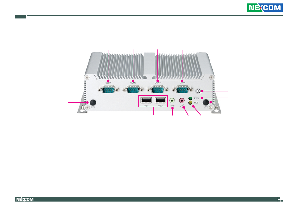
Knowing Your NISE 104
Antenna Hole
HDD LED
Line-out
USB
Mic-in
Power Switch
Antenna Hole
Power LED
COM1
(RS232)
COM2
(RS232/422/485)
COM3
(RS232/422/485)
COM4
(RS232)
Power Switch
Press to power-on or power-off the system.
Power Status LED
Indicates the system’s power status.
HDD Activity LED
Indicates the hard drive’s activity.
COM1 and COM4 RS232
Used to connect RS232 compatible devices.
COM2 and COM3 RS232/RS422/RS485
Used to connect RS232/422/485 compatible serial devices.
USB2.0 Ports
Two USB2.0 ports to connect the system with USB2.0/1.1 devices.
Line-out
Line-out jack to connect speakers or headphones.
Mic-in
Mic-in jack to connect microphones.
Antenna Holes
Empty antenna holes reserved for installing optional Mini-PCIe Wi-Fi
module.
Front Panel