Top view, Chapter 2: jumpers and connectors, Nise 301 user manual – NEXCOM NISE 301 User Manual
Page 22: Jp10, Jp12, Jp8 cn2 cn9
Advertising
Copyright © 2015 NEXCOM International Co., Ltd. All Rights Reserved.
8
NISE 301 User Manual
Chapter 2: Jumpers and Connectors
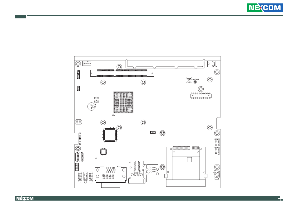
Locations of the Jumpers and Connectors for NISB 301
The figures below are the top and bottom views of the NISB 301 main board used in NISE 301. It shows the locations of the jumpers and connectors.
2
20
19
1
16
1
9
8
24
17
39
34
29
35
30
25
BJ
BH
AU
AW
BG
BA
BC
BE
AE
AG
AJ
AL
AN
AR
R
U W
AA
AC
C
E
G
J
L
N
53
51
49
47
45
43
41
39
37
35
33
31
29
27
25
23
21
19
17
15
13
11
9
7
A
5
3
1
U10
204
203
74
73
72
71
2
DIMM1
2
1
JP3
1
6
5
1
5
JP7
1
10
J3
1
10
J4
65
64
33
32
97
96
12
8
1
U19
3
1
JP6
3
1
JP4
1
JP2
J3
J4
JP11
POWER
1
4
JP10
1
4
JP9
4
CN1
5
4
10
9
12
4
9
1
B10
O
G
A10
Y
36
24
25
37
48
1
12
U27
2
6
JP1
LED3
LED2
1
JP12
1
1
4
JP8
CN2
CN9
3
1
3
3
1
LED4
JP13
CN5
CN4
CN3
COP1A (LAN1)
COP2A (LAN2)
VGA
DVI-D
LAN1
LAN2
USB 2.0
CFAST
1
2
1
1
2
Top View
Advertising