NEXCOM NEX 716VL2G User Manual
Page 20
19
Chapter 2
NEX716VL2G User Manual
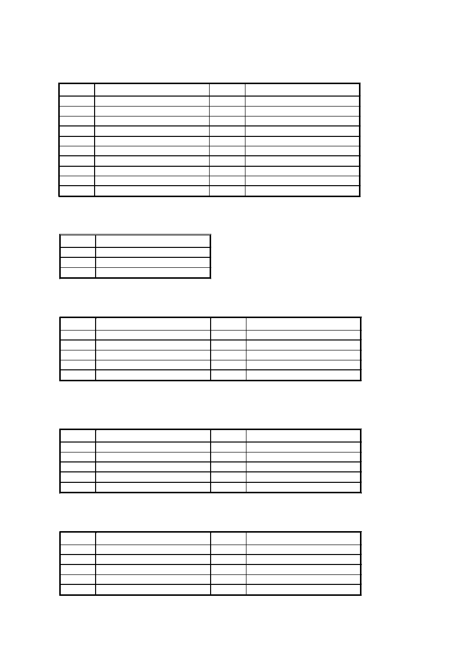
J12: ATX Power Connector, 10x2 pin
J5/J35/J36: CPU Fan/ System Fan1/System Fan2 Connector
Pin No.
Description
1
Ground
2
Programmable Fan Power
3
Fan Speed sensor
J7/J9/J13: COM2(RS232 Mode )/COM3/COM4, 5X2 Pin Box Header
Pin No.
Description
Pin No.
Description
1
DCD
6
DSR
2
RXD
7
RTS
3
TXD
8
CTS
4
DTR
9
RI
5
Ground
10
NC
J7: COM2 RS422 Mode
Pin No.
Description
Pin No.
Description
1
TXD-
6
RTS-
2
TXD+
7
RTS+
3
RXD+
8
CTS+
4
RXD-
9
CTS-
5
Ground
10
NC
J7: COM2 RS485 Mode
Pin No.
Description
Pin No.
Description
1
TXD-/RXD-
6
NA
2
TXD+/RXT+
7
NA
3
NA
8
NA
4
NA
9
NA
5
Ground
10
NC
Pin No.
Description
Pin No.
Description
11
+3.3V
1
+3.3V
12
-12V
2
+3.3V
13
Ground
3
Ground
14
PS-ON
4
+5V
15
Ground
5
Ground
16
Ground
6
+5V
17
Ground
7
Ground
18
-5V
8
Power Good
19
+5V
9
+5VSB
20
+5V
10
+12V