NEXCOM NEX 716VL2G User Manual
Page 21
20
Chapter 2
NEX716VL2G User Manual
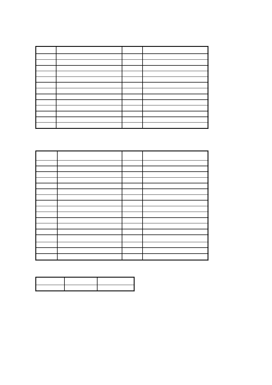
J8: LPT1 (Parallel Port), DSUB 25 Pin Connector.
Pin No.
Description
Pin No.
Description
1
Line Print Strobe
14
Auto Feed
2
Parallel Data 0
15
Error
3
Parallel Data 1
16
Initialize
4
Parallel Data 2
17
Select
5
Parallel Data 3
18
Ground
6
Parallel Data 4
19
Ground
7
Parallel Data 5
20
Ground
8
Parallel Data 6
21
Ground
9
Parallel Data 7
22
Ground
10
Acknowledge
23
Ground
11
Busy
24
Ground
12
Paper empty
25
Ground
13
Select
26
NC
J10: FDD,17x2 Box Header.
Pin No.
Description
Pin No.
Description
1
Ground
2
DENSEL#
3
Ground
4
NC
5
Ground
6
NC
7
Ground
8
INDEX#
9
Ground
10
MOTEA#
11
Ground
12
DRVB#
13
Ground
14
DRVA#
15
Ground
16
MOTEB#
17
Ground
18
DIR#
19
Ground
20
STEP#
21
Ground
22
WDATA#
23
Ground
24
WGATE#
25
Ground
26
TK00#
27
Ground
28
WPT#
29
NC
30
RDATA#
31
Ground
32
SIDE1#
33
NC
34
DSKCHG#
J14: IDE Access LED Header, 2x1 Pin Header.
Pin No.
1
2
Description
LED+
LED-