NEXCOM NEX 883 User Manual
Page 26
Advertising
Copyright © 2011 NEXCOM International Co., Ltd. All Rights Reserved.
15
Chapter 2: Installation
NEX 883 User Manual
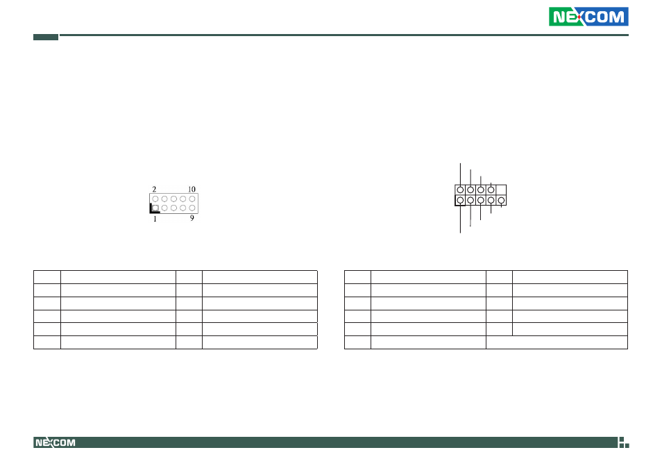
Digital Input/ Output Pin Header
(9-pin JGPIO1)
(see p.8, No.16)
Please connect the CPU fan cable to the connector and match the
black wire to the ground pin.
Pin
Signal Name
Pin
Signal Name
1
Digital Output 0
2
Digital Input 0
3
Digital Output 1
4
Digital Input 1
5
Digital Output 2
6
Digital Input 2
7
Digital Output 3
8
Digital Input 3
9
JGPIO_PWR1
10
GND
System Panel Header
(9-pin PANEL1)
(see p.8, No.22)
This header accommodates system front panel functions.
GND
GND
PWRBTN#
PLED-
PLED+
RESET#
HDLED-
HDLED+
1
DUMMY
Pin
Signal Name
Pin
Signal Name
1
HDLED+
2
HDLED-
3
GND
4
RESET#1
5
DUMMY
6
PLED+
7
PLED-
8
PWRBTN#
9
GND
Advertising