System fan1 connector power button, System fan1 connector, Power button – NEXCOM IPPC 1560T User Manual
Page 68
Advertising
Copyright © 2014 NEXCOM International Co., Ltd. All Rights Reserved.
51
IPPC 1560T/1960T/2160P Series User Manual
Chapter 2: Jumpers and Connectors
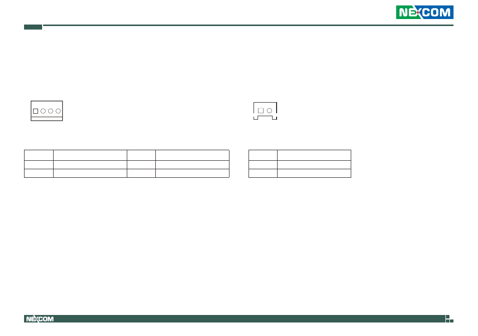
Pin
Definition
Pin
Definition
1
GND
2
12V
3
SYSFANIN
4
SYSFANOUT
System FAN1 Connector
Connector type: 1x4 4-pin Wafer, 2.54mm pitch
Connector location: CN18
1
4
Pin
Definition
1
HW_R_RST#
2
GND
Power Button
Connector type: 1x2 JST, 2-pin header, 2.0mm pitch
Connector location: J7
1
2
Advertising
This manual is related to the following products: