Mini pci-e connector – NEXCOM VTC 100 User Manual
Page 27
Advertising
Copyright © 2013 NEXCOM International Co., Ltd. All rights reserved
14
VTC 100 User Manual
Chapter 2: Jumpers and Connectors
Pin
In/Output
Function
Voltage Levels
1,3
IN
Microphone
5,7
OUT
Speaker Out
11
OUT
GSM Module VREF OUT
1.8V or 2.6V
17
OUT
PCM Data Out
19
OUT
PCM Sync Out
32
OUT
SMS RI Out, for wake up system
33
IN
RESET#
45
OUT
PCM CLK Out
47
IN
PCM Data In
49
OUT
UART Receive Data (GSM Module need to connect to TX)
51
IN
UART Transmit Data (GSM Module need to connect to RX)
36,38
IN/OUT
USB
20
IN
Module Disable (Low)
42
OUT
WWAN LED
8,10,12,14
IN/OUT
SIM Card
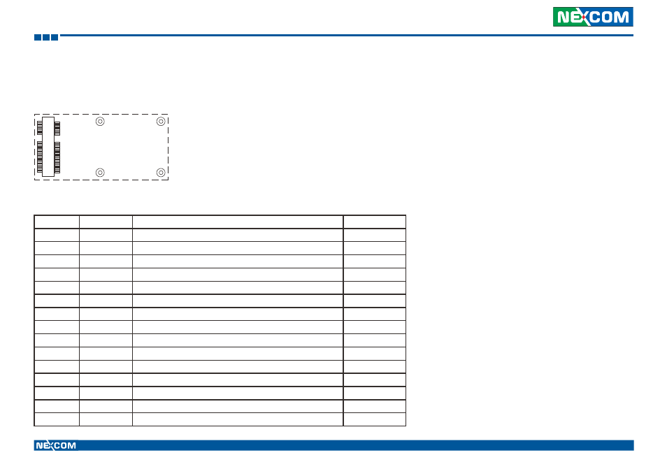
Mini PCI-E Connector
Connector location: CN2
51
1
52
2
Important Pin Assignments
Advertising