Gpio and can bus 2.0b connector – NEXCOM VTC 1000 User Manual
Page 24
Copyright © 2011 NEXCOM International Co., Ltd. All Rights Reserved.
11
Chapter 2: External Connectors Pinout Description
VTC 1000 User Manual
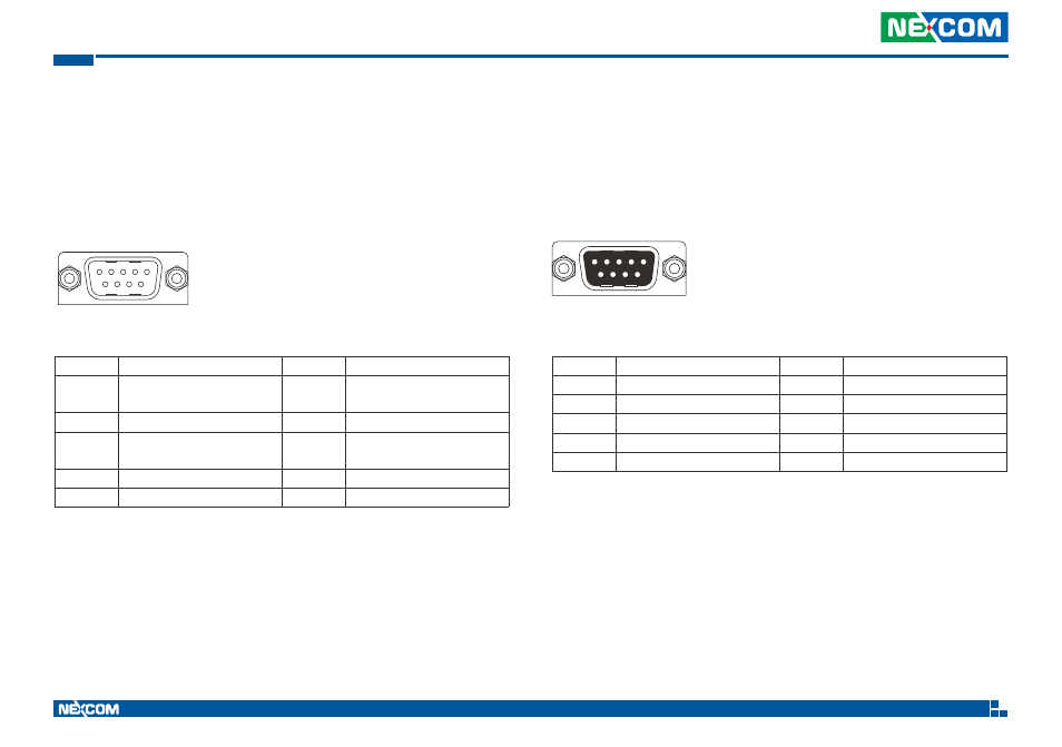
COM2 Connector RS422/485
Connector size: DB9, Male
Connector Number: 11
(2x RS485<Default>) or
(2x RS422) or (1x RS422 + 1x RS485) selected by BIOS setting
Pin
Definition
Pin
Definition
1
RS422_RX+_A
RS485_+_A
2
RS422_RX-_A
RS485_-_A
3
RS422_TX+_A
4
RS422_TX-_A
5
GND
6
RS422_RX-_B /
RS485_+_B
7
RTS/ RS485_RX-
8
RS422_TX+_B
9
RS422_TX-_B
1
5
6
9
Pin
Definition
Pin
Definition
1
INPUT_1 PORT
2
INPUT_2 PORT
3
INPUT_3 PORT
4
INPUT_4 PORT
5
GND
6
OUTPUT_1 PORT
7
OUTPUT_2 PORT / CAN_H
8
OUTPUT_3 PORT / CAN_L
9
OUTPUT_4 PORT
5
1
9
6
GPIO and CAN Bus 2.0B Connector
Connector size: DB9, Female
Connector Number: 12
4x GPI, 2x GPO, 1x CAN Bus 2.0B (Default). 4x GPO can be selected by BIOS setting.