Appendix 1 (projected area values), 103im, 106im – One Systems Pole Mount Mini User Manual
Page 9
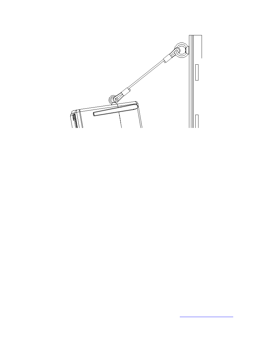
Figure 5
Figure 5 is a close up view of the wire rope assembly. One end is connected to
the M8 eyebolt on the Pole Mount Mini and the other end to the eyebolt mounted
to the enclosure (103IM shown in Figure 5, for the 108IM the eyebolt in located
on the rear of the enclosure near the top).
Note: The ¼ inch thimbles must be spread slightly to fit over the eyebolts and
then recompressed.
APPENDIX 1
(Projected Area Values)
The values below should be supplied to the specific pole manufacturer for safety
calculations. These values were determined by adding the projected areas of the
high frequency horns, the woofer cones and ports to the cross sectional area of
the front of each enclosure listed below.
103IM …………………………….
67 in^2 (43,000 mm^2)
106IM…………………………….
136 in^2 (88,000mm^2)
The products referenced in this manual are in conformity with the following
standards or other normative documents: Machinery Directive 2006/42/EC
© One Systems, Inc. 2014 (revision of 2011 edition)