Mda-26 callouts, Page 3 – Oxmoor MDA-16 User Manual
Page 5
Page 3
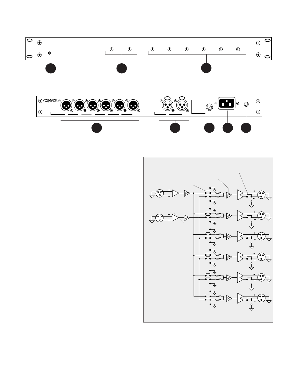
MDA-26 CALLOUTS
FUSE
POWER
CHASSIS
SERIAL NUMBER
D
C
B
A
OUTPUT
CAUTION REPLACE ONLY
WITH SAME TYPE FUSE
1/8 A SB @ 115V
1/16 A SB @ 230 V
F
E
INPUT
1
2
OXMOOR
MDA-26 DISTRIBUTION AMPLIFIER
CHANNEL 1
CHANNEL A
CHANNEL B
CHANNEL C
CHANNEL D
CHANNEL E
CHANNEL F
CHANNEL 2
POWER
1
3
Figure 2.0: MDA-26 Front Panel View
Figure 2.1: MDA-26 Rear Panel View
8
7
6
4
1.
POWER STATUS LED – Indicator for AC Power On.
2.
INPUT TRIMS – Trim pots, accessed through the front panel
with a small flat-blade screwdriver, adjust the input stage gain,
±
15 dB, to compensate for varying input signal levels.
3.
OUTPUT TRIM – Trim pots, accessed through the front
panel with a small flat-blade screwdriver. These controls
provide
±
15 dB of gain adjustment for matching different
operating levels or balancing levels across channels.
4.
PROGRAM OUTPUTS – Audio outputs, XLR-M–type
connectors, Pin 2 positive, electronically balanced, accept
balanced or unbalanced signals. Recommended load
impedance is 600 ohms or greater. Maximum output level
is +26 dBu.
5.
PROGRAM INPUTS – Audio inputs, XLR-F–type connectors,
electronically balanced, accept balanced or unbalanced signals
from line-level devices. Normal input level is +4 dBu with a
maximum input level of +24 dBu.
6.
FUSE HOLDER – Replace only with approved type of fuse
in a rating appropriate to the mains voltage, as indicated
on back panel. (See SPECIFICATIONS.)
7.
POWER CONNECTOR – Standard IEC 3-pin connector
for AC power cord. Use only with grounded (3-wire) outlets.
Cord sets are available for all world connection standards.
8.
CHASSIS GROUND POST – A screw with a star washer
enables the installer to secure a ground wire to the
chassis.
Figure 2.2: MDA-26 Block Diagram
2
5
3
3
2
1
INPUT 1
3
INPUT 2
3
2
1
2
1
OUTPUT A
OUTPUT B
OUTPUT C
OUTPUT D
OUTPUT E
OUTPUT F
ON
OFF
2
1
2
1
2
1
2
1
2
1
2
1
2
1
2
1
2
1
2
1
2
1
3
3
3
3
BALANCED/UNBALANCED OUTPUT JUMPER
CHANNEL ASSIGNMENT
OUTPUT TRIM
INPUT TRIM