Mda connections, Mda program output connections, Mda program input wiring schemes – Oxmoor MDA-16 User Manual
Page 7: Mda program output wiring schemes, Mda program input connections, Refer to figure 5.0 and 5.1), Page 5, Unbalanced balanced
Page 5
MDA CONNECTIONS
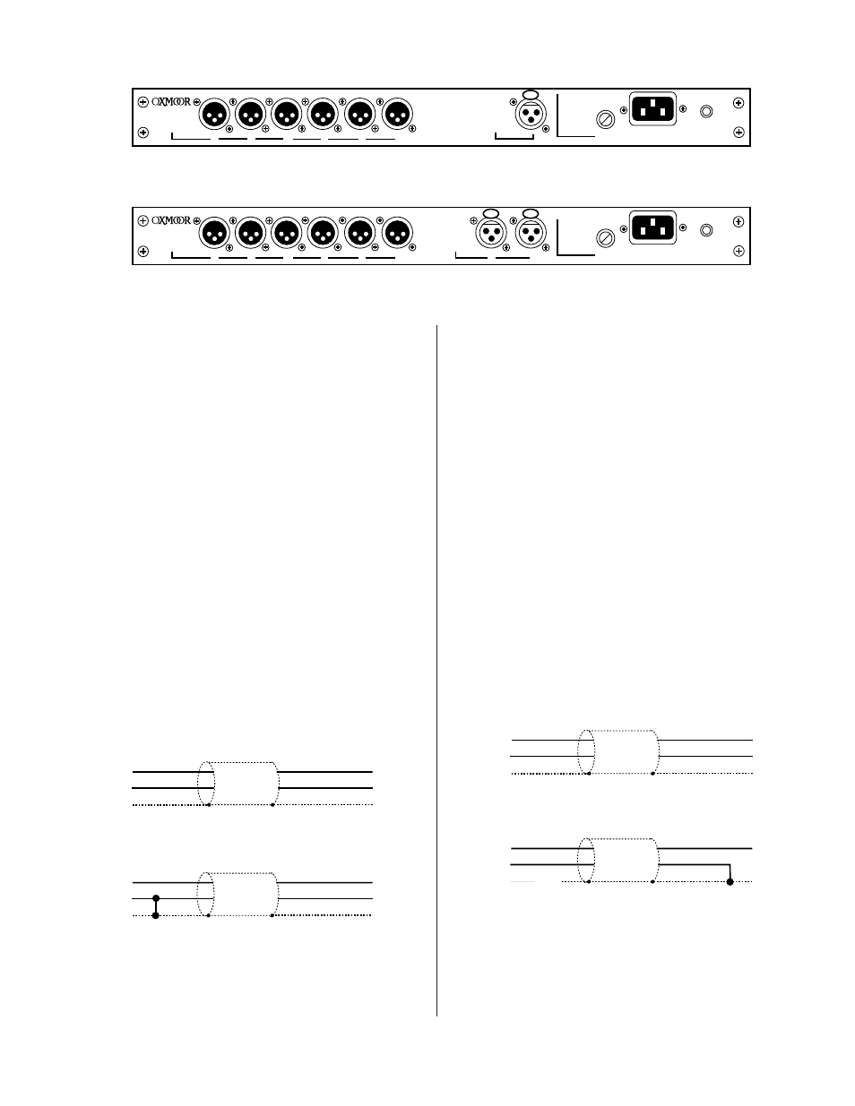
Figure 5.0: MDA-16 Program Input and Outputs View
Figure 5.3: MDA Program Output Wiring Schemes
Figure 5.1: MDA-26 Program Inputs and Outputs View
MDA PROGRAM OUTPUT CONNECTIONS
(Refer to Figure 5.0 and 5.1)
MDA-16 and MDA-26 Distribution Amplifiers provide
connections for six program channels out.
Program Output connections on both the MDA-16 and
MDA-26 are made through male, XLR-type, 3-pin connec-
tors.
PROGRAM OUTPUTS
: Pin 1 = Shield, Pin 2 = High, Pin
3 = Low, electronically balanced outputs accommodate
balanced or unbalanced lines. Recommended load imped-
ance is 600 ohms or greater. Maximum output level is +26
dBu.
MDA PROGRAM INPUT WIRING SCHEMES
(Refer to Figures 5.2)
The diagrams below illustrate the correct wiring of bal-
anced and unbalanced program inputs.
MDA PROGRAM OUTPUT WIRING SCHEMES
(Refer to Figures 5.3)
The diagrams below illustrate the correct wiring of bal-
anced and unbalanced program outputs.
NOTE: The unbalanced output configuration is valid ONLY if the
Balanced/Unbalanced output jumper block has been set to the
unbalanced position. See page 4, Figure 3.0.
BALANCED
UNBALANCED
PIN 2 POSITIVE
ON ALL AUDIO
CONNECTIONS
FUSE
POWER
CHASSIS
SERIAL NUMBER
D
C
B
A
OUTPUT
INPUT
CAUTION REPLACE ONLY
WITH SAME TYPE FUSE
1/8 A SB @ 115V
1/16 A SB @ 230 V
F
E
FUSE
POWER
CHASSIS
SERIAL NUMBER
D
C
B
A
OUTPUT
CAUTION REPLACE ONLY
WITH SAME TYPE FUSE
1/8 A SB @ 115V
1/16 A SB @ 230 V
F
E
INPUT
1
2
LOW
HIGH
Pin 2
Pin 3
Pin 1
Pin 2
Pin 3
Pin 1
SHIELD
HIGH
LOW
NC
Pin 2
Pin 3
Pin 1
Pin 2
Pin 3
Pin 1
HIGH
LOW
SHIELD
HIGH
LOW
NC
UNBALANCED
BALANCED
MDA PROGRAM INPUT CONNECTIONS
(Refer to Figure 5.0 and 5.1)
The MDA-16 Distribution Amplifier provides connec-
tions for one program channel input while the MDA-26
Distribution Amplifier provides connections for two pro-
gram channel inputs.
Each Program Input connection on the MDA-16 and
MDA-26 is made through a female, XLR-type, 3-pin con-
nector.
PROGRAM INPUTS
: Pin 1 = Shield, Pin 2 = High, Pin
3 = Low, electronically balanced inputs, accept balanced
or unbalanced signals from line-level devices. Nominal
input level is +4 dBu with maximum input level of + 24
dBu.
Figure 5.2: MDA Program Input Wiring Schemes