Renegade race kit install, 1 supercharger mounting br, Renegade race kit installation -1 – Paxton Superchargers Mustang Renegade Class User Manual
Page 5: Supercharger mounting bracket installation -1, Renegade race kit installation
P/N: 4809622a
©2006 Paxton Automotive
All Rights Reserved, Intl. Copr. Secured
07SEP06 v2.0 MusRenegade(4809622a v2.0)
1-1
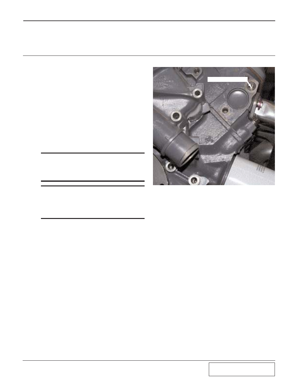
P/N 33 ATTACHES HERE
7-Bolt Points for the S/C Bracket
X
X
X
X
X
X
X
Before beginning the installation of your super-
charger, the engine should have all of its acces-
sory drive components removed.
1.1
SUPERCHARGER MOUNTING
BRACKET INSTALLATION
A.
If you have not already done so, remove the
alternator.
1
.
Disconnect the battery
2
.
Relieve tension on the drive belt
3
.
Remove the belt
4
.
Remove the alternator
5
.
Remove the water pump pulley
B
.
Install mounting bracket. (See Appendix “B”,
mounting bracket assembly.)
*** NOTE ***
We suggest that you assemble the mounting bracket
in an organized fashion, keeping the parts in order, as
is shown in Appendix “B”. It is especially critical to
keep the proper spacers and washers together with
their bolts. Refer to Appendix “B” for there locations.
*** NOTE ***
Leave out the spacers (items #11, #40, and #41) in
the initial installation of the mounting bracket. After
the complete installation of the bracket, slip the spac-
ers into place. If the spacers do not fit snugly, the
spacers will have to be machined. This is due to the
factory variations of the engine.
Section 1
RENEGADE RACE KIT INSTALLATION
Fig. 1-a
C.
Place the triangular spacer (item #12) against
the cylinder head, and attach the back plate
(item #3) to the engine block using the 2.5" x
7/16" screw and washer, (items #33, #34). The
screw passes throught the spacer and into the
cylinder head at the point shown. (See
Fig. 1-a.)
D.
Slip the spacers (items #5, #6) into the counter-
bored holes in the back plate.
E.
Attach the small triangular bracket (item #8) to
the lower part of the timing cover using bolts
(items #26, #27). (See Fig. 1-a.)